0.8mm Pitch, Compact and Robust Wire-to-Board Connectors
DF52 Series
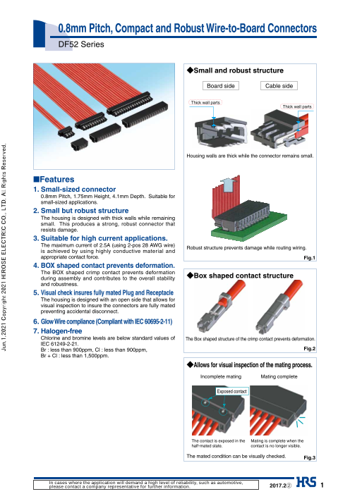
◆Small and robust structure
Board side Cable side
Thick wall parts
Thick wall parts
Housing walls are thick while the connector remains small.
■Features
1. Small-sized connector
0.8mm Pitch, 1.75mm Height, 4.1mm Depth. Suitable for
small-sized applications.
2. Small but robust structure
The housing is designed with thick walls while remaining
small. This produces a strong, robust connector that
resists damage.
3. Suitable for high current applications.
The maximum current of 2.5A (using 2-pos 28 AWG wire)
Robust structure prevents damage while routing wiring.
is achieved by using highly conductive material and
appropriate contact force. Fig.1
4. BOX shaped contact prevents deformation.
The BOX shaped crimp contact prevents deformation
during assembly and contributes to the overall stability ◆Box shaped contact structure
and robustness.
5. Visual check insures fully mated Plug and Receptacle
The housing is designed with an open side that allows for
visual inspection to insure the connectors are fully mated
preventing accidental disconnect.
6. Glow Wire compliance (Compliant with IEC 60695-2-11)
7. Halogen-free
Chlorine and bromine levels are below standard values of The Box shaped structure of the crimp contact prevents deformation.
IEC 61249-2-21.
Br : less than 900ppm, Cl : less than 900ppm, Fig.2
Br + Cl : less than 1,500ppm.
◆Allows for visual inspection of the mating process.
Incomplete mating Mating complete
Exposed contact
The contact is exposed in the Mating is complete when the
half-mated state. contact is no longer visible.
The mated condition can be visually checked. Fig.3
In cases where the application will demand a high level of reliability, such as automotive,
please contact a company representative for further information. 2017.2② 1
Jun.1.2021 Copyright 2021 HIROSE ELECTRIC CO., LTD. All Rights Reserved.
DF52 Series●0.8mm Pitch, Compact and Robust Wire-to-Board Connectors
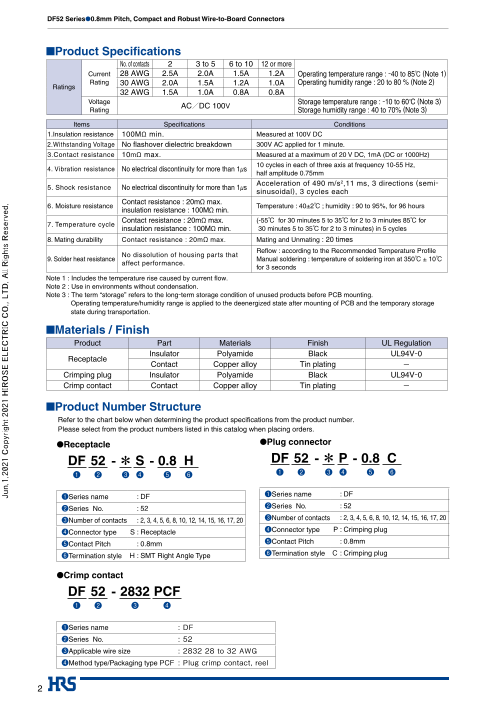
■Product Specifications
No. of contacts 2 3 to 5 6 to 10 12 or more
Current 28 AWG 2.5A 2.0A 1.5A 1.2A Operating temperature range : -40 to 85℃ (Note 1)
Rating 30 AWG 2.0A 1.5A 1.2A 1.0A Operating humidity range : 20 to 80 % (Note 2) Ratings
32 AWG 1.5A 1.0A 0.8A 0.8A
Voltage / Storage temperature range : -10 to 60°C (Note 3) Rating AC DC 100V Storage humidity range : 40 to 70% (Note 3)
Items Specifications Conditions
1.Insulation resistance 100MΩ min. Measured at 100V DC
2.Withstanding Voltage No flashover dielectric breakdown 300V AC applied for 1 minute.
3.Contact resistance 10mΩ max. Measured at a maximum of 20 V DC, 1mA (DC or 1000Hz)
μ 10 cycles in each of three axis at frequency 10-55 Hz,4. Vibration resistance No electrical discontinuity for more than 1 s
half amplitude 0.75mm
Acceleration of 490 m/s2,11 ms, 3 directions (semi-
5. Shock resistance No electrical discontinuity for more than 1μs
sinusoidal), 3 cycles each
Contact resistance : 20mΩ max.
6. Moisture resistance Ω Temperature : 40±2℃ ; humidity : 90 to 95%, for 96 hoursinsulation resistance : 100M min.
Contact resistance : 20mΩ max. (-55℃ for 30 minutes 5 to 35℃ for 2 to 3 minutes 85℃ for
7. Temperature cycle
insulation resistance : 100MΩ min. 30 minutes 5 to 35℃ for 2 to 3 minutes) in 5 cycles
8. Mating durability Contact resistance : 20mΩ max. Mating and Unmating : 20 times
Reflow : according to the Recommended Temperature Profile
No dissolution of housing parts that
9. Solder heat resistance Manual soldering : temperature of soldering iron at 350℃ ± 10℃
affect performance.
for 3 seconds
Note 1 : Includes the temperature rise caused by current flow.
Note 2 : Use in environments without condensation.
Note 3 : The term “storage” refers to the long-term storage condition of unused products before PCB mounting.
Operating temperature/humidity range is applied to the deenergized state after mounting of PCB and the temporary storage
state during transportation.
■Materials / Finish
Product Part Materials Finish UL Regulation
Insulator Polyamide Black UL94V-0
Receptacle
Contact Copper alloy Tin plating -
Crimping plug Insulator Polyamide Black UL94V-0
Crimp contact Contact Copper alloy Tin plating -
■Product Number Structure
Refer to the chart below when determining the product specifications from the product number.
Please select from the product numbers listed in this catalog when placing orders.
●Receptacle ●Plug connector
DF 52 - * S - 0.8 H DF 52 - * P - 0.8 C
❶ ❷ ❸ ❹ ❺ ❻ ❶ ❷ ❸ ❹ ❺ ❻
❶Series name : DF ❶Series name : DF
❷Series No. : 52 ❷Series No. : 52
❸Number of contacts : 2, 3, 4, 5, 6, 8, 10, 12, 14, 15, 16, 17, 20 ❸Number of contacts : 2, 3, 4, 5, 6, 8, 10, 12, 14, 15, 16, 17, 20
❹Connector type S : Receptacle ❹Connector type P : Crimping plug
❺Contact Pitch : 0.8mm ❺Contact Pitch : 0.8mm
❻Termination style H : SMT Right Angle Type ❻Termination style C : Crimping plug
●Crimp contact
DF 52 - 2832 PCF
❶ ❷ ❸ ❹
❶Series name : DF
❷Series No. : 52
❸Applicable wire size : 2832 28 to 32 AWG
❹Method type/Packaging type PCF : Plug crimp contact, reel
2
Jun.1.2021 Copyright 2021 HIROSE ELECTRIC CO., LTD. All Rights Reserved.
DF52 Series●0.8mm Pitch, Compact and Robust Wire-to-Board Connectors
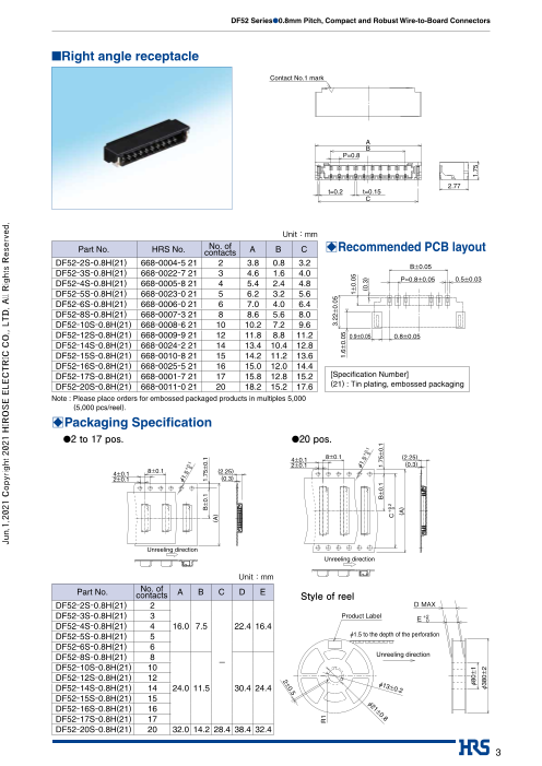
■Right angle receptacle
Contact No.1 mark
A
B
P=0.8
2.77
t=0.2 t=0.15
C
Unit:mm
Part No. HRS No. No. of A B C BRecommended PCB layoutcontacts
DF52-2S-0.8H(21) 668-0004-5 21 2 3.8 0.8 3.2 B±0.05
DF52-3S-0.8H(21) 668-0022-7 21 3 4.6 1.6 4.0
P=0.8±0.05 0.5±0.03
DF52-4S-0.8H(21) 668-0005-8 21 4 5.4 2.4 4.8
DF52-5S-0.8H(21) 668-0023-0 21 5 6.2 3.2 5.6
DF52-6S-0.8H(21) 668-0006-0 21 6 7.0 4.0 6.4
DF52-8S-0.8H(21) 668-0007-3 21 8 8.6 5.6 8.0
DF52-10S-0.8H(21) 668-0008-6 21 10 10.2 7.2 9.6
DF52-12S-0.8H(21) 668-0009-9 21 12 11.8 8.8 11.2 0.9±0.05 0.8±0.05
DF52-14S-0.8H(21) 668-0024-2 21 14 13.4 10.4 12.8
DF52-15S-0.8H(21) 668-0010-8 21 15 14.2 11.2 13.6
DF52-16S-0.8H(21) 668-0025-5 21 16 15.0 12.0 14.4
DF52-17S-0.8H(21) 668-0001-7 21 17 15.8 12.8 15.2 [Specification Number]
DF52-20S-0.8H(21) 668-0011-0 21 20 18.2 15.2 17.6 (21) : Tin plating, embossed packaging
Note : Please place orders for embossed packaged products in multiples 5,000
(5,000 pcs/reel).
BPackaging Specifi cation
●2 to 17 pos. ●20 pos.
4±0.1 8±0.1 (2.25)
2±0.1 (0.3)
4±0.1 8±0.1 (2.25)
2±0.1 (0.3)
Unreeling direction
Unreeling direction
Unit:mm
Part No. No. of contacts A B C D E Style of reel
DF52-2S-0.8H(21) 2 D MAX
DF52-3S-0.8H(21) 3 Product Label E +20
DF52-4S-0.8H(21) 4 16.0 7.5 22.4 16.4
DF52-5S-0.8H(21) 5 Ø1.5 to the depth of the perforation
DF52-6S-0.8H(21) 6
DF52-8S-0.8H(21) 8 Unreeling direction-
DF52-10S-0.8H(21) 10
DF52-12S-0.8H(21) 12
Ø
DF52-14S-0.8H(21) 14 24.0 11.5 30.4 24.4 13±0.2
DF52-15S-0.8H(21) 15 Ø2
DF52-16S-0.8H(21) 16 1±0.
DF52-17S-0.8H(21) 17 8
DF52-20S-0.8H(21) 20 32.0 14.2 28.4 38.4 32.4
3
Jun.1.2021 Copyright 2021 HIROSE ELECTRIC CO., LTD. All Rights Reserved.
Ø1.5 +0
0 .1
B±0.1 1.75±0.1
(A)
R1
3.22±0.05
1.6±0.05
1±0.05
Ø1.5 +0
0 .1 (0.3)
B±0.1 1.75±0.1
C+0.20
(A)
Ø80±1 1.75
Ø380±2
.5
2±
0
DF52 Series●0.8mm Pitch, Compact and Robust Wire-to-Board Connectors
■Crimping plug
A
P=0.8 1
B 1.65
**
Contact No.1 mark One mark for every 5 pins
Unit:mm
Part No. HRS No. No. of contacts A B
DF52-2P-0.8C 668-0013-6 00 2 0.8 3.5
DF52-3P-0.8C 668-0026-8 00 3 1.6 4.3
DF52-4P-0.8C 668-0014-9 00 4 2.4 5.1
DF52-5P-0.8C 668-0027-0 00 5 3.2 5.9
DF52-6P-0.8C 668-0015-1 00 6 4.0 6.7
DF52-8P-0.8C 668-0016-4 00 8 5.6 8.3
DF52-10P-0.8C 668-0017-7 00 10 7.2 9.9
DF52-12P-0.8C 668-0018-0 00 12 8.8 11.5
DF52-14P-0.8C 668-0028-3 00 14 10.4 13.1
DF52-15P-0.8C 668-0019-2 00 15 11.2 13.9
DF52-16P-0.8C 668-0029-6 00 16 12.0 14.7
DF52-17P-0.8C 668-0002-0 00 17 12.8 15.5 [Specification Number]
DF52-20P-0.8C 668-0020-1 00 20 15.2 17.9 None : 100 pcs/pack
Note : Please specify the number of packs (100 pcs/pack) when placing orders.
■Crimp contact
0.6 0.66
t=0.12
1.4 [Specification Number]
None : 40,000 pcs/reel
P=4
Part No. HRS No. Type Quantity Finish
DF52-2832PCF 668-0030-5 00 Reel contact 40,000 pcs/reel Tin plating
Note 1 : This product is sold in 40,000 piecies per reels. Please place orders in multiples of 40,000.
●Applicable wire (Tinned Annealed Copper Wire)
Conductor size (Core structure) Jacket outer diameter Recommended wire Strip length
28 AWG (7 pieces/0.127mm in diameter)
30 AWG (7 pieces/0.102mm in diameter) Ø0.5 to 0.6mm UL1571 (thin line) 0.9 to 1.3mm
32 AWG (7 pieces/0.08mm in diameter)
Note : Please contact our Sales representative when using wires other than applicable wires.
Note : The strip length is a reference value. Please adjust the strip length accordingly for specifications and requirements.
Refer to the crimping quality standard (ATAD-H0789) for details.
4
Jun.1.2021 Copyright 2021 HIROSE ELECTRIC CO., LTD. All Rights Reserved.
(6.18)
3.8
3
2.68
1.35 3.2
0.3 0.65
DF52 Series●0.8mm Pitch, Compact and Robust Wire-to-Board Connectors
BApplicable crimping tools
Type Part No. HRS No. Applicable contact Remarks
AP105-DF52-2832P 901-4636-7 DF52-2832PCF
Applicator (Note 2) Manufactured by Japan
DHS877900H-UP - DF52-2832PCF
Automatic Machine Co.,Ltd.
Press body CM-105C 901-0001-0 00 -
Pull-out tool DF-C-PO(B) 550-0179-2 00 DF52-2832PCF
Note 1 : Issues caused by using other than our specified tools are not covered by warranty.
Note 2 : A pplicator manufactured by JAPAN AUTOMATIC MACHINE (J.A.M.). Please access to HP of J.A.M., if you
make inquiries about the applicator or crimp defect. (URL : http://www.jam-net.co.jp)
BPrecautions
1. Recommended
Temperature Profile 10sec MAX
(Compatible with lead- MAX 250℃
free soldering) 250
220℃
200
180℃
150
100
0
90-120sec 60sec MAX TIME (Sec)
PRE-HEATING TIME SOLDERING TIME
[Applicable Conditions]
1. Peak temperature : 250℃ max.
2. Heating area : 220℃ min. for less than 60 seconds
3. Preheating area : 150℃ to 180℃ for 90 to 120 seconds
4. Number of times : no more than 2 times
* Measurement is conducted at the contact lead part
Soldering results may change depending on conditions such as solder
paste type, manufacturer, PCB size, and other soldering materials. Please
determine all mounting conditions before use.
Note 1 : This temperature profile is a recommended value.
2. Recommended Temperature of soldering iron : 350±10℃, soldering time : within 3 seconds
manual soldering
conditions
3. Recommended screen Thickness : 0.1mm, aperture opening ratio : 100%
thickness and
aperture ratio
(Pattern surface ratio)
4. Warpage of the Board A maximum of 0.02mm at the center of connector, as measured from either
end of the connector
5. Cleaning Conditions IPA cleaning is allowed. (Cleaning is not recommended due to potential changes in
mating action and other variables. Please contact us if you use other cleaning agents. )
6. Noteworthy Points ■Please note that any mating operation of the connector when not mounted
on the board may cause damage or deformation of the contacts.
■During hand soldering, do not apply flux, as it will flow over the connector.
■This housing color may have slight variations depending on the production
lot. This color variation does not affect performance.
■Please refer to “DF52 mating and unmating Procedure Document
(ETAD-H0788)” for points in handling regarding mating operations.
■Please refer to “Harness procedure manual (ETAD-H0791)” for points in
harness operations.
5
Jun.1.2021 Copyright 2021 HIROSE ELECTRIC CO., LTD. All Rights Reserved.
TEMPERATURE(℃)
DF52 Series●0.8mm Pitch, Compact and Robust Wire-to-Board Connectors
USA: USA: USA:
HIROSE ELECTRIC (U.S.A.), INC. HEADQUARTERS CHICAGO OFFICE HIROSE ELECTRIC (U.S.A.), INC. SAN JOSE OFFICE HIROSE ELECTRIC (U.S.A.), INC. DETROIT OFFICE (AUTOMOTIVE)
2300 Warrenville Road, Suite 150, 2841 Junction Ave, Suite 200 17197 N. Laurel Park Drive, Suite 253,
Downers Grove, IL 60515 San Jose, CA. 95134 Livonia, MI 48152
Phone : +1-630-282-6700 Phone : +1-408-253-9640 Phone : +1-734-542-9963
http://www.hirose.com/us/ Fax : +1-408-253-9641 Fax : +1-734-542-9964
http://www.hirose.com/us/ http://www.hirose.com/us/
THE NETHERLANDS: GERMANY: GERMANY:
HIROSE ELECTRIC EUROPE B.V. HIROSE ELECTRIC EUROPE B.V. GERMAN BRANCH HIROSE ELECTRIC EUROPE B.V. NUREMBERG OFFICE
Hogehillweg #8 1101 CC Amsterdam Z-O Schoenbergstr. 20, 73760 ostfildern Neumeyerstrasse 22-26, 90411 Nurnberg
Phone : +31-20-6557460 Phone : +49-711-456002-1 Phone : +49-911 32 68 89 63
Fax : +31-20-6557469 Fax : +49-711-456002-299 Fax : +49-911 32 68 89 69
http://www.hirose.com/eu/ http://www.hirose.com/eu/ http://www.hirose.com/eu/
GERMANY: FRANCE: UNITED KINGDOM:
HIROSE ELECTRIC EUROPE B.V. HANOVER OFFICE HIROSE ELECTRIC EUROPE B.V. PARIS OFFICE HIROSE ELECTRIC EUROPE BV (UK BRANCH)
Bayernstr. 3, Haus C 30855 Langenhagen, Germany Regus La Garenne Colombes,Place de La Belgique, 4 Newton Court, Kelvin Drive, Knowlhill,
Phone : +49-511 97 82 61 30 71 Boulevard National La Garenne Colombes, 92250, France Milton Keynes, MK5 8NH
Fax : +49-511 97 82 61 35 Phone : +33 (0) 1 7082 3170 Phone : +44-1908 202050
http://www.hirose.com/eu/ Fax : +33 (1) 7082 3101 Fax : +44-1908 202058
http://www.hirose.com/eu/ http://www.hirose.com/eu/
CHINA: CHINA: CHINA:
HIROSE ELECTRIC (SHANGHAI) CO., LTD. HIROSE ELECTRIC (SHANGHAI) CO.,LTD. BEIJING BRANCH HIROSE ELECTRIC TECHNOLOGIES (SHENZHEN) CO., LTD.
1601, Henderson Metropolitan, NO.300, East Nanjing A1001, Ocean International Center, Building 56# East 4th Room 09-13, 19/F, Office Tower Shun Hing Square, Di Wang Commercial Centre,
Road, Huangpu District, Shanghai, China 200001 Ring Middle Road, ChaoYang District, Beijing, 100025 5002 Shen Nan Dong Road, Shenzhen City, Guangdong Province, 518008
Phone : +86-21-6391-3355 Phone : +86-10-5165-9332 Phone : +86-755-8207-0851
Fax : +86-21-6391-3335 Fax : +86-10-5908-1381 Fax : +86-755-8207-0873
http://www.hirose.com/cn/ http://www.hirose.com/cn/ http://www.hirose.com/cn/
HONG KONG: TAIWAN: KOREA:
HIROSE ELECTRIC HONGKONG TRADING CO., LTD. HIROSE ELECTRIC TAIWAN CO., LTD. HIROSE KOREA CO.,LTD.
Room 1001, West Wing, Tsim Sha Tsui Centre, 66 103 8F, No.87, Zhengzhou Rd., Taipei 250, Huimanggongwon-ro, Siheung-si,
Mody Road, Tsim Sha Tsui East, Kowloon, Hong Kong Phone : +886-2-2555-7377 Gyeonggi-do, Korea, 15083
Phone : +852-2803-5338 Fax : +886-2-2555-7350 Phone : +82-31-496-7000 or 7124
Fax : +852-2591-6560 http://www.hirose.com/tw/ Fax : +82-31-496-7100
http://www.hirose.com/hk/ http://www.hirose.co.kr/
SINGAPORE: INDIA: INDIA:
HIROSE ELECTRIC SINGAPORE PTE. LTD. HIROSE ELECTRIC SINGAPORE PTE. LTD. DELHI LIAISON OFFICE HIROSE ELECTRIC SINGAPORE PTE. LTD. BANGALORE LIAISON OFFICE
10 Anson Road #26-16, International Plaza Office NO.552, Regus-Green Boulevard, Level5, Tower C, Unit No-403, 4th Floor, No-84, Barton Centre, Mahatma
079903, Singapore Sec62, Plot B-9A, Block B, Noida, 201301, Uttar Pradesh, India Gandhi (MG) Road, Bangalore 560 001, Karnataka, India
Phone : +65-6324-6113 Phone : +91-12-660-8018 Phone : +91-80-4120 1907
Fax : +65-6324-6123 Fax : +91-120-4804949 Fax : +91-80-4120 9908
http://www.hirose.com/sg/ http://www.hirose.com/sg/ http://www.hirose.com/sg/
MALAYSIA: THAILAND:
PENANG REPRESENTATIVE OFFICE BANGKOK OFFICE (REPRESENTATIVE OFFICE)
1-21-01, Suntech @ Penang Cybercity (1164), Lintang Unit 4703, 47th FL., 1 Empire Tower, South Sathorn
Mayang Pasir 3,11950, Bayan Baru, Penang, Malaysia. Road, Yannawa, Sathorn, Bangkok 10120 Thailand
Phone : +604-619-2564 Phone : +66-2-686-1255
Fax : +604-619-2574 Fax : +66-2-686-3433
http://www.hirose.com/sg/ http://www.hirose.com/sg/
® 2-6-3,Nakagawa Chuoh,Tsuzuki-Ku,Yokohama-Shi 224-8540,JAPAN
TEL: +81-45-620-3526 Fax: +81-45-591-3726
http://www.hirose.com
http://www.hirose-connectors.com
The characteristics and the specifications contained herein are for reference purpose. Please refer to the latest customer drawings prior to use.
6 The contents of this catalog are current as of date of 02/2017. Contents are subject to change without notice for the purpose of improvements.
Jun.1.2021 Copyright 2021 HIROSE ELECTRIC CO., LTD. All Rights Reserved.


