1/6ページ
Download(544.6Kb)
SEMAPHORE INDICATOR SPSR TYPE, SPSL TYPE
Product Catalog
Document Information
| Document Title | SEMAPHORE INDICATOR SPSR TYPE, SPSL TYPE |
|---|---|
| Document Type | Product Catalog |
| File size | 544.6Kb |
| Category | |
| Company | FUJI ELECTRIC INDUSTRY CO., LTD. (Documents List) |
Documents related to this company

Document Contents
Page1
● インジケーター
SEMAPHORE RELAY SEMAPHORE INDICATOR
SPR TYPE, SPL TYPE SPSR TYPE, SPSL TYPE
SPR-3□
8 97 (screw type 100)
t=1 to 6mm
+0.5 R2 +0.5
φ30.5- 0 φ30.5 -0
G R
COM
Panel Applicable receptacle F type FT type (with rotation stopper)
#205 series mounting hole mounting hole
11
100 +0.5 R2
φ30.5- 0
+0.5
φ30.5 -0
3-M3×6
Screw φ27.8
φ38 S type ST type (with rotation stopper)
mounting hole mounting hole
SPR-4□
8 97 (screw type 100)
t=1 to 6mm
+0.5 R2 +0.5
φ30.5- 0 φ30.5 -0
G R
COM
Panel Applicable receptacle F type FT type (with rotation stopper)
#205 series mounting hole mounting hole
11
100 +0.5 R2 +0.5
φ30.5- 0 φ30.5 -0
3-M3×6
Screw φ27.8
φ38 S type ST type (with rotation stopper)
mounting hole mounting hole
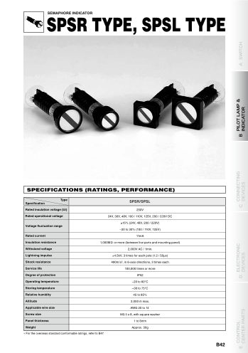
SPECIFICATIONS (RATINGS, PERFORMANCE)
SPL-3 □
9.5 95.5 (screw type 98.5) Type
Specification SPSR/SPSL
t=1 to 6mm
+0.5 R2 +0.5
φ30.5 -0 φ30.5 -0 Rated insulation voltage (Ui) 250V
G R
Rated operational voltage 24V, 30V, 48V, 100 / 110V, 125V, 200 / 220V DC
COM
±15% (24V, 48V, 200 / 220V)
Panel Applicable receptacle F type FT type (with rotation stopper)
#205 series mounting hole mounting hole Voltage fluctuation range
–20 to 30% (100 / 110V, 125V)
11
100 +0.5 R2 +0.5
φ30.5 -0 φ30.5 -0 Rated current 11mA
Insulation resistance 1,000MΩ or more (between live parts and mounting panel)
3-M3×6 Withstand voltage 2,000V AC / 1min.
Screw φ27.8
φ38 S type ST type (with rotation stopper)
mounting hole mounting hole Lightning impulse ±4.5kV, 3 times for each pole (1.2 / 50µs)
Shock resistance 490m/s2, in 6-axis directions, 3 times each
SPL-4 □ Service life 100,000 times or more
9.5 95.5 (screw type 98.5) Degree of protection IP52
t=1 to 6mm
+0.5 R2 +0.5 Operating temperature –20 to 60°C
φ30.5 -0 φ30.5 -0
G R Storing temperature –30 to 75°C
COM Relative humidity 45 to 85%
Panel Applicable receptacle F type FT type (with rotation stopper)
#205 series mounting hole mounting hole Altitude 2,000 m max.
11 Applicable wire size
100 +0.5 R2 +0.5 AWG 20 to 14
φ30.5 -0 φ30.5 -0
Screw size M3.5 x 8, with square washer
Panel thickness 1 to 6mm
3-M3×6
Screw φ27.8
φ38 S type ST type (with rotation stopper) Weight Approx. 30g
mounting hole mounting hole
For the overseas standard conformable ratings, refer to B47.
B42
φ40 φ33 φ34 φ28
□43 □35 φ40
φ33
5.5 4.5 5.5 4.5 5.5 4.5 5.5 4.5
E CONTROL D ELECTRONIC DEVICES C
CONNECTING
DEVICES B
PILOT LAMP &
CENTER PARTS INDICATOR A SWITCH
Page2
SEMAPHORE INDICATOR
SPSR TYPE, SPSL TYPE
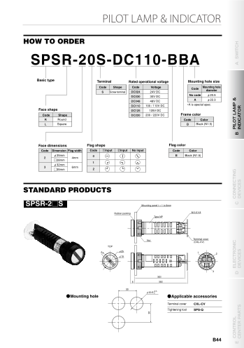
FEATURES HOW TO ORDER
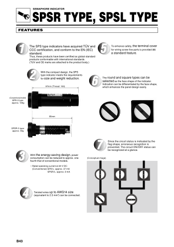
1 The SPS type indicators have acquired TÜV and To enhance safety, the terminal cover SPSR-20S-DC110-BBA
CCC certification, and conform to the EN (IEC) for wiring screw live parts is provided as
standard. 5 a standard feature.
Thus, these products have been certified as global standard Basic type Terminal Rated operational voltage Mounting hole size
products conformable with international standards.
(TUV and CE marks are attached to the product body.) Code Shape Code Voltage Code Mounting hole
S Screw terminal DC024 24V DC diameter
DC030 30V DC No code φ20.5
2 With the compact design, the SPS DC048 48V DC A φ22.3
type indicator meets the requirements DC110 100 / 110V DC ∗A is special spec.
for size and weight reduction. 6 The round and square types can be Face shape DC125 125V DC
selected as the face shape of the indicator. Code Shape DC220 200 / 220V DC Frame color
Indication can be differentiated by the face shape, R Round Code Color
97mm (Thread: 100) which enhances the panel design easily. L Square B Black (N1.5)
(Conventional model)
SPR-3 type:
approx. 125g Face dimensions Flag shape Flag color
Code Dimension Flag width Code ①Input ②Input No input Code Color
φ25mm B Black (N1.5)
4mm 0
2
□28mm
85mm 1
φ32mm
3 6mm
□35mm 2
SPSR-3 type:
approx. 30g
STANDARD PRODUCTS
7 Since the circuit status is indicated by the
flag shape, erroneous recognition is SPSR-2□S Mounting panel t = 1 to 6mm
prevented. The circuit ON/OFF sta tus can
be recognized at a glance.
Rubber packing M 3.5×8
3 With the energy-saving design, power Type NP
consumption can be reduced to approx. one (Conceptual image)
fourth that of conventional models.
∗ Rated operating current at 24 V DC:
(Conventional) SPR/L: approx. 37 mA
Nut Terminal cover
SPSR/L: approx. 9 mA (CXL-CV)
TOP
4 φ25 1 2
φ19
4 Twisted wires up to AWG14 size 3
(equivalent to 2.5 mm2) can be connected. (80)
6 (85)
30
φ20.5 +0.5 -0
●Mounting hole ●Applicable accessories
Terminal cover CXL-CV
Tightening tool SPS-Q
B43
30
Page3
SEMAPHORE INDICATOR
SPSR TYPE, SPSL TYPE
FEATURES HOW TO ORDER
1 The SPS type indicators have acquired TÜV and To enhance safety, the terminal cover SPSR-20S-DC110-BBA
CCC certification, and conform to the EN (IEC) for wiring screw live parts is provided as
standard. 5 a standard feature.
Thus, these products have been certified as global standard Basic type Terminal Rated operational voltage Mounting hole size
products conformable with international standards.
(TUV and CE marks are attached to the product body.) Code Shape Code Voltage Code Mounting hole
S Screw terminal DC024 24V DC diameter
DC030 30V DC No code φ20.5
2 With the compact design, the SPS DC048 48V DC A φ22.3
type indicator meets the requirements DC110 100 / 110V DC ∗A is special spec.
for size and weight reduction. 6 The round and square types can be Face shape DC125 125V DC
selected as the face shape of the indicator. Code Shape DC220 200 / 220V DC Frame color
Indication can be differentiated by the face shape, R Round Code Color
97mm (Thread: 100) which enhances the panel design easily. L Square B Black (N1.5)
(Conventional model)
SPR-3 type:
approx. 125g Face dimensions Flag shape Flag color
Code Dimension Flag width Code ①Input ②Input No input Code Color
φ25mm B Black (N1.5)
2 4mm 0
□28mm
85mm 1
φ32mm
3 6mm
□35mm 2
SPSR-3 type:
approx. 30g
STANDARD PRODUCTS
7 Since the circuit status is indicated by the
flag shape, erroneous recognition is SPSR-2□S Mounting panel t = 1 to 6mm
prevented. The circuit ON/OFF sta tus can
be recognized at a glance.
Rubber packing M 3.5×8
3 With the energy-saving design, power Type NP
consumption can be reduced to approx. one (Conceptual image)
fourth that of conventional models.
∗ Rated operating current at 24 V DC:
(Conventional) SPR/L: approx. 37 mA
Nut Terminal cover
SPSR/L: approx. 9 mA (CXL-CV)
TOP
4 φ25 1 2
φ19
4 Twisted wires up to AWG14 size 3
(equivalent to 2.5 mm2) can be connected. (80)
6 (85)
30
φ20.5 +0.5 -0
●Mounting hole ●Applicable accessories
Terminal cover CXL-CV
Tightening tool SPS-Q
B44
30
E CONTROL D ELECTRONIC DEVICES C
CONNECTING
CENTER PARTS DEVICES B
PILOT LAMP &
INDICATOR A SWITCH
Page4
SEMAPHORE INDICATOR
SPSR TYPE, SPSL TYPE
STANDARD PRODUCTS
SPSR-3□S Mounting panel t = 1 to 6mm SPSL-3□S Mounting panel t = 1 to 6mm
Rubber packing Rubber packing
M 3.5×8 M 3.5×8
Type NP Type NP
Nut Terminal cover Terminal cover
Nut
(CXL-CV) (CXL-CV)
TOP
6 φ32 6 TOP
1
1 2 2
φ26 φ26
3
3
(80) 35 (80)
8.5 (85) 9.5 (85)
40 40
φ20.5 +0.5 -0 φ20.5 +0.5 -0
●Mounting hole ●Applicable accessories ●Mounting hole ●Applicable accessories
Terminal cover CXL-CV Terminal cover CXL-CV
Tightening tool SPS-Q Tightening tool SPS-Q
SPSL-2□S Mounting panel t = 1 to 6mm ACCESSORIES
Rubber packing M 3.5×8
Type NP Terminal cover (Order unit: 10) Tightening tool
●CXL-CV ●SPS-Q
∗ Tighting tool for a nut.
Nut Terminal cover
(CXL-CV)
TOP
4 1
2
φ19
∗ The terminal cover is provided as standard
equipment.
3
28
(80)
7 (85)
30
φ20.5 +0.5 -0
●Mounting hole ●Applicable accessories
Terminal cover CXL-CV
Tightening tool SPS-Q
B45
28
30
40
35
40
Page5
SEMAPHORE INDICATOR
SPSR TYPE, SPSL TYPE
STANDARD PRODUCTS
SPSR-3□S Mounting panel t = 1 to 6mm SPSL-3□S Mounting panel t = 1 to 6mm
Rubber packing Rubber packing
M 3.5×8 M 3.5×8
Type NP Type NP
Nut Terminal cover Terminal cover
Nut
(CXL-CV) (CXL-CV)
TOP 6 TOP
6 φ32
1
1 2 2
φ26 φ26
3
3
(80) 35 (80)
8.5 (85) 9.5 (85)
40 40
φ20.5 +0.5
-0 φ20.5 +0.5-0
●Mounting hole ●Applicable accessories ●Mounting hole ●Applicable accessories
Terminal cover CXL-CV Terminal cover CXL-CV
Tightening tool SPS-Q Tightening tool SPS-Q
SPSL-2□S Mounting panel t = 1 to 6mm ACCESSORIES
Rubber packing M 3.5×8
Type NP Terminal cover (Order unit: 10) Tightening tool
●CXL-CV ●SPS-Q
∗ Tighting tool for a nut.
Nut Terminal cover
(CXL-CV)
TOP
4 1
2
φ19
∗ The terminal cover is provided as standard
equipment.
3
28
(80)
7 (85)
30
φ20.5 +0.5 -0
●Mounting hole ●Applicable accessories
Terminal cover CXL-CV
Tightening tool SPS-Q
B46
28
30
40
35
40
E CONTROL D ELECTRONIC DEVICES C
CONNECTING
CENTER PARTS DEVICES B
PILOT LAMP &
INDICATOR A SWITCH
Page6
SEMAPHORE INDICATOR 全方向屋外表示器
SPSR TYPE, SPSL TYPE LUSO形 , USO形
OPERATION AND CIRCUIT SPECIFICATIONS
●Operation chart ●Circuit diagram
①Input ②Input No voltage
DC DC DC DC
(P) (P) (P) (P)
1 2 1 2 1 2 1 2
R R
OFF SD SD ON
Coil Coil
R
3 3 3 Semaphore
3 relay
(N) (N) (N) (N)
OVERSEAS STANDARD CONFORMABLE RATINGS (EN60947/IEC60947)
(1) Basic ratings and applications
No. Item Basic rating and application IEC standard No.
1 Rated operational voltage 24V, 48V, 100 / 110V, 125V, 200 / 220V DC IEC60947-5-1; 5.1-d
2 Rated operational current 11mA max. IEC60947-5-1; 5.1-e 特長
3 Rated insulation voltage (Ui) 250V IEC60947-5-1; 5.1-f ■屋外用全方向視タイプの表示器
4 IP code IP 52 IEC60947-5-1; 5.1-I 360°死角のない表示器で、遮断器等の開閉表示をはじめ試験設備、生産設備、駐車場などの幅広い用途にご使用いた
だけます。
(2) Normal operating conditions
■耐候性にすぐれた樹脂を採用
No. Item Normal operating condition IEC standard No.
屋外使用に耐える高性能ポリカーボネイト樹脂をレンズに採用し、鮮明な色彩を長期間保つことができます。
1 Ambient temperature ‒5℃ to 40℃ IEC60947-1; 6.1.1
■高輝度LEDタイプ(LUSO形 )
2 Altitude 2,000 m max. IEC60947-1; 6.1.2
昼間でも点灯識別の可能な高輝度LEDを採用し、ロングライフを実現しました。
3 Atmospheric condition Humidity: 90% max. (at 20℃), 50% (at 40℃)
Microscopic environment: Pollution degree: 3 IEC60947-1; 6.1.3
仕様(定格・性能 )
4 Conditions during ‒25℃ to 55℃
transport and strage +70℃ for short periods (within 24 hours) IEC60947-1; 6.2
仕様 形式 LUSO(LED式) USO(白熱灯式)
5 Mounting of single hole mounted devices φ20.5mm IEC60947-5-1; 6.3.1
Range of panel thickness 定格絶縁電圧
6 1 to 6mm IEC60947-5-1; 6.3.1.2 250V
Minimum distances between SPSR/L-2□ 30mm 定格使用電圧 DC48V,DC100/110V,AC100/110V,AC200/220V AC・DC100/110V,200/220V
7 centres of mounting holes IEC60947-5-1; 6.3.1.3
SPSR/L-3□ 40mm 耐 電 圧 ( 充電部一括対 取付パネル間) AC2,500V/1分間
雷インパルス ( 充電部一括対 取付パネル間) ±7kV/各極3回(1.2/50μs)
(3) Structure and performance
絶 縁 抵 抗 絶縁抵抗計(DC500V)100MΩ以上
No. Item Structure and performance IEC standard No.
Twisted wire: AWG20 (2 pieces max.) IEC60947-1; 7.1.7 耐 衝 撃 性 50G
1 Connecting capacity
Round crimp terminal: AWG14 to 20 (2 pieces max.) IEC60947-1; AnnexD 使用周囲温度 -25~55 ℃
2 Withstand voltage Power-frequency withstand voltage: 2,000V AC / 1min. IEC60947-5-1; 7.2.3 保 存 温 度 -40~85 ℃
3 Durability Mechanical durability: 100,000 operations IEC60947-5-1; AnnexC 使 用 状 態 標高2,000m以下、屋外使用可(但し塩害地域を除く)
Remarks: The SPS type indicators have acquired TÜV certification for the above items. For detailed information, contact Fuji Electric Industry.
B47


