


EtherCAT通信対応のリモートI/O
省配線・省スペース、各モジュールにEtherCATチップを内蔵。
多様なモジュールを用意、組合せが多彩。
センサー、ステッピングモータ、ランプなどのデバイスに対応。
モジュールの選択肢はDI (16点)、DO (16点、PNP/NPN)、AI (4点)、AO (4点)、パルス出力 (1軸)
関連メディア
このカタログについて
| ドキュメント名 | デルタ電子 EtherCAT通信対応リモートI/O R1-ECシリーズ |
|---|---|
| ドキュメント種別 | 製品カタログ |
| ファイルサイズ | 1.5Mb |
| 登録カテゴリ | |
| 取り扱い企業 | デルタ電子株式会社 (この企業の取り扱いカタログ一覧) |
この企業の関連カタログ


このカタログの内容
Page1
Automation for a Changing World
Delta PC-Based
Motion Controller
PAC Total Solution
www.del taww.com
Page2
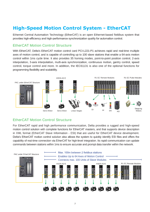
Ethernet Central Automation Technology (EtherCAT) is an open Ethernet-based fieldbus system that
EtherCAT Motion Control Structure
With EtherCAT, Delta's EtherCAT motion control card PCI-L221-P1 achieves rapid and real-time multiple
axes of motion control, and is capable of controlling up to 100 slave stations that enable a 64-axis motion
control within 1ms cycle time. It also provides 35 homing modes, point-to-point position control, 2-axis
control, torque control and more. In addition, the IEC61131 is also one of the optional functions for
ASDA-A2-E R1-EC Remote Modules R1-EC Pulse Modules
PAC under EtherCAT Structure
Stepping
Servo Motor Servo Motor DILinear Stages AI DO AO Motors
EtherCAT Motion Control Structure
For EtherCAT rapid and high performance communication, Delta provides a rugged and high-speed
motion control solution with complete functions for EtherCAT masters, and that supports device description
in XML format (EtherCAT Slave Information - ESI) that are useful for EtherCAT device development.
capability of real-time connection via EtherCAT for high-level integration. Its rapid communication can update
commands between stations within 1ms to ensure accurate and prompt data transfer within the network.
PAC under EtherCAT Structure
Enables Up to 64 Axes of Motion Control
Connects max. 100 Units of Slave Modules
ASDA-A2-E ASDA-A2-E R1-EC Remote Modules
7
Page3
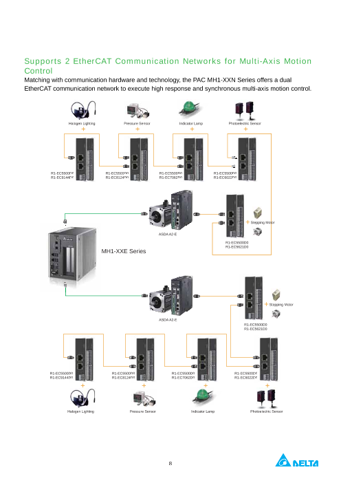
Supports 2 EtherCAT Communication Networks for Multi-Axis Motion
Control
Matching with communication hardware and technology, the PAC MH1-XXN Series offers a dual
EtherCAT communication network to execute high response and synchronous multi-axis motion control.
Halogen Lighting Pressure Sensor Indicator Lamp Photoelectric Sensor
+ + + +
R1-EC5500D0 R1-EC5500D0 R1-EC5500D0 R1-EC5500D0
R1-EC9144D0 R1-EC8124D0 R1-EC7062D0 R1-EC6022D0
+Stepping Motor
ASDA A2-E
R1-EC5500D0
R1-EC5621D0
MH1-XXE Series
+Stepping Motor
ASDA A2-E
R1-EC5500D0
R1-EC5621D0
R1-EC5500D0 R1-EC5500D0 R1-EC5500D0 R1-EC5500D0
R1-EC9144D0 R1-EC8124D0 R1-EC7062D0 R1-EC6022D0
+ + + +
Halogen Lighting Pressure Sensor Indicator Lamp Photoelectric Sensor
8
Page4
EtherCAT Automation Software
and debugging. For new users of Delta's EtherCAT motion control, the EcNavi helps
and validation in real time.
Hardware Structure Search
Provides search function for all slaves connected by
whether the network communication is established
successfully via software
Speed Curve Tracing
Offers real-time tracing for speed curves of current
effects between multiple axes
21
Page5
Independent Control Unit
Assists users avoid writing complex programs and
servo drives to meet application requirements
Multi-Axis Motion Control Mode
Offers a variety of sample programs and control modes
for EtherCAT devices (e.g. Linear 2, Linear 3, Heli,
Circle, Circle 2 and Circle 3) to help users easily edit and
complete development programs for multi-axis motion
control applications
22
Page6
Gateway Type E-bus Remote Power Coupler
R1-EC5500D0 / R1-EC5512D0
W: 25mm W: 25mm
E E
D D
C NO. Description
A. DC Power Input
B B. EtherCAT Output
C. EtherCAT Input
D. Status Indicator
A A E. Power Indicator
H: 74mm H: 74mm
Technical Data R1-EC5500D0 R1-EC5512D0
Task Within EtherCAT System Connect EtherCAT Slave module with 100 baseTX EtherCAT
Data Transfer Medium Ethernet/EtherCAT cable (min. CAT 5), shielded -
Distance Between Stations 100 M (100BASE-TX) between two slaves -
Protocol EtherCAT
Data Transfer Rates 100 Mbaud
Bus Interface RJ 45 x 2 -
Input Voltage 24 VDC
Input Current 50 mA + (E-bus total E-bus current)/4
Current Supply E-Bus 2 A
Electrical Isolation 500 Vrms (Power contact / Supply voltage / Ethernet)
Vibration / Shock Resistance EN 60068-2-6 / EN 60068-2-27 / 29
ESD (IEC 61131-2, IEC 61000-4-2): 8KV Air Discharge
EMC Immunity EFT (IEC 61131-2, IEC 61000-4-4): Power Line: 2KV Communication I/O: 1KV
Operating Environment Operating temperature: 0 ºC ~ 50 ºCStorage temperature: -20 ºC ~ 70 ºC
Weight 55 g
Protection Class IP20
Mounting Type DIN-rail
41
L: 100mm
L: 100mm
Page7
1-Channel Pulse Output Remote Module
R1-EC5621D0
W: 17.5 mm F NO. Description No. Description
E A. IO Signal Port D. IO Signal Indicator
D B. IO Signal Port E. Status Indicator
C C. IO Signal Indicator F. Power Indicator
Input Description Input Description
B 24V 24V Power GND External Ground
MEL End Limit (-) QA+ Encoder A Phase (+)
PEL End Limit (+) QA- Encoder A Phase (-)
ORG Home Signal QB+ Encoder B Phase (+)
A ALM Servo Alarm QB- Encoder B Phase (-)
SON Servo On PA+ Pulse Signal (+)
H: 74 mm CLR Reset Servo Alarm PA- Pulse Signal (-)
QZ+ Encoder Z Phase (+) PB+ Dir. Signal (+)
QZ- Encoder Z Phase (-) PB- Dir. Signal (-)
Technical Data R1-EC5621D0
Number of Outputs 1 channel PA+, PA-, PB+, PB-
Number of Inputs 1 channel (QA+, QA-, QB+, QB-. QZ+, QZ-)
Power Supply Supplied by E-bus
Signal Voltage RS422 Level
Max. Output Current
Base Frequency
Numbers of 24 V Input 4 ( MEL, PEL, ORG, ALM)
Numbers of 24 V Output 2 ( CLR, SON)
Trigger Voltage (On > Off) 8 VDC
Trigger Voltage (Off > On) 16.5 VDC
Maximum Current of Each Output Port 30 mA
Current Consumption E-Bus 150 mA
Electrical Isolation
Bit Width in the Process Image 32 byte in/out (1 x 16 byte data, 1 x 16 byte control/status)
Vibration / Shock Resistance EN 60068-2-6 / EN 60068-2-27 / 29
ESD (IEC 61131-2, IEC 61000-4-2): 8 KV Air Discharge
EMC Immunity EFT (IEC 61131-2, IEC 61000-4-4): Power Line: 2 KV Communication I/O: 1 KV
Operating Environment Operating temperature: 0 ºC ~ 50 ºCStorage temperature: -20 ºC ~ 70 ºC
Weight Approx. 60 g
Protection Class IP20
Mounting Type DIN-rail
42
L: 100 mm
Page8
16-Channel Input Remote Module
R1-EC6002D0 / R1-EC6022D0
W: 17.5 mm
F NO Description NO. Description
E
D A. Port 1 Terminals D.
Port 1 IO Signal
X08 ~ X15 (From the top)
C B. Port 0 Terminals E. Status Indicator
C. Port 0 IO SignalX00 ~ X07 (From the top) F. Power Indicator
B
Input Description Input Description
CM0 Port 0 COM CM1 Port1 COM
X00 Input 0 X08 Input 8
A X01 Input 1 X09 Input 9
X02 Input 2 X10 Input 10
X03 Input 3 X11 Input 11
H: 74 mm X04 Input 4 X12 Input 12
X05 Input 5 X13 Input 13
X06 Input 6 X14 Input 14
X07 Input 7 X15 Input 15
Technical Data R1-EC6002D0 R1-EC6022D0
Connection Technology single-ended
Number of Inputs 16
Nominal Voltage 24 VDC 10%
Signal Type SINK / SOURCE
Trigger Voltage (On > Off) < 8 VDC
Trigger Voltage (Off > On) > 16.5 VDC
Input Filter 100 s 2ms
Input Current 3 mA at each port
Current Consumption E-Bus 110 mA
Electrical Isolation
Bit Width in the Process Image 16 inputs
Vibration / Shock Resistance EN 60068-2-6 / EN 60068-2-27 / 29
ESD (IEC 61131-2, IEC 61000-4-2): 8 KV Air Discharge
EMC Immunity EFT (IEC 61131-2, IEC 61000-4-4): Power Line: 2 KVCommunication I/O: 1 KV
Operating Environment Operating temperature: 0 ºC ~ 50 ºCStorage temperature: -20 ºC ~ 70 ºC
Weight 55 g
Protection Class IP20
Mounting Type DIN-rail
43
L: 100 mm
Page9
16-Channel Output Remote Module
R1-EC7062D0 / R1-EC70E2D0 / R1-EC70A2D0 / R1-EC70F2D0
W: 17.5mm
F NO. Description NO. Description
E
D A. Port 1 Terminals D.
Port 1 IO Signal
Y08 ~ Y15 (From the top)
C B. Port 0 Terminals E. Status Indicator
C. Port 0 IO SignalY00 ~ Y07 (From the top ) F. Power Indicator
B
Output Description Output Description
GND* Port 0 GND
** GND Port 1 GND24V Port 0 24V Input
A Y00 Input 0 Y08 Input 8
Y01 Input 1 Y09 Input 9
Y02 Input 2 Y10 Input 10
H: 74mm Y03 Input 3 Y11 Input 11
Y04 Input 4 Y12 Input 12
Y05 Input 5 Y13 Input 13
Y06 Input 6 Y14 Input 14
Y07 Input 7 Y15 Input 15
* R1-EC7062D0 / R1-EC70E2D0
** R1-EC70A2D0 / R1-EC70F2D0
Technical Data R1-EC7062D0 R1-EC70E2D0 R1-EC70A2D0 R1-EC70F2D0
Connection Technology MOSFET
Signal Type SINK SOURCE
Nominal Voltage 24 VDC
Maintains Output X X
Input Current 0.5A (Max.) 0.25A (Max.)
Current Consumption E-Bus 120mA 200mA
Response Time / Frequency
Trigger Time (OFF > ON) 140us 160us
Trigger Time (ON > OFF) 150us 110us
ESD (IEC 61131-2, IEC 61000-4-2): 8 KV Air Discharge
EMC Immunity EFT (IEC 61131-2, IEC 61000-4-4): Power Line: 2 KVCommunication I/O: 1 KV
Operating Environment Operating temperature: 0 ºC ~ 50 ºCStorage temperature : -20 ºC ~ 70 ºC
Weight Approx. 60 g
Protection Class IP20
Mounting Type DIN-rail
44
L: 100mm
Page10
4-Channel Analog Input Remote Module
R1-EC8124D0
W: 17.5 mm
F NO. Description NO. Description
E A. CH3/CH4 Signal port D. CH3/CH4 Signal Indicator
D B. CH1/CH2 Signal port E. Status Indicator
C C. CH1 Voltage / Current Input F. Power Indicator
B Input Description Input Description
GND Analog Ground GND Analog Ground
AI0 CH1 Voltage /Current Input AI2 CH3 Voltage / Current Input
GND Analog Ground GND Analog Ground
A AG0 CH1 Current COM* AG2 CH3 Current COM*
GND Analog Ground GND Analog Ground
AI1 CH2 Voltage / Current Input AI3 CH4 Voltage / Current Input
H: 74 mm GND Analog Ground GND Analog Ground
AG1 CH2 Current COM* AG3 CH4 Current COM*
GND Analog Ground GND Analog Ground
* In current mode: please connect current COM to GND ; In voltage mode: please disconnect this COM
Technical data R1-EC8124D0
Number of Inputs 4 (single-ended)
Power Supply via the E-bus
Signal Voltage 10 V / 5 V
Internal Resistance > 1 M
Input Filter Limit Frequency
Resolution 16 bit
Over Sampling Rate 0 ~ 64
Conversion Time 2 us ~ 191 us (depends on Over Sampling Rate)
Measuring Error < 0.2 % (relative to full scale value)
Electrical Isolation 500 Vrms (E-bus / signal voltage)
Current Consumption E-Bus 300 mA
Bit Width in the Process Image input 4 x 16 byte data, 4 x 16 byte control/status
Vibration / Shock Resistance 60068-2-6 / EN 60068-2-27 / 29
ESD (IEC 61131-2, IEC 61000-4-2): 8 KV Air Discharge
EMC Immunity EFT (IEC 61131-2, IEC 61000-4-4): Power Line: 2 KVCommunication I/O: 1 KV
Operating Environment Operating temperature: 0 ºC ~ 50 ºCStorage temperature: -20 ºC ~ 70 ºC
Weight Approx. 60 g
Protection Class IP20
Mounting Type DIN-rail
45
L: 100 mm
Page11
4-Channel Analog Output Remote Module
R1-EC9144D0
W: 17.5 mm
F NO. Description NO. Description
E A. CH3/CH4 Signal Port D. CH3/CH4Signal Indicator
D B. CH1/CH2 Signal Port E. Status Indicator
C
C. CH1/CH2 Signal Indicator F. Power Indicator
B Output Description Output Description
GND Analog Ground GND Analog Ground
VO0 CH1 Voltage Output VO2 CH3 Voltage Output
GND Analog Ground GND Analog Ground
A IO0 CH1 Current Output IO2 CH3 Current Output
GND Analog Ground GND Analog Ground
VO1 CH2 Voltage Output VO3 CH4 Voltage Output
H: 74 mm GND Analog Ground GND Analog Ground
IO1 CH2 Current Output IO3 CH4 Current Output
GND Analog Ground GND Analog Ground
Technical Data R1-EC9144D0
Number of Inputs 4 (single-ended)
Power Supply via the E-bus
Signal Voltage Output 10 V / 5 V / 0 ~ 5 V / 0 ~ 10 V
Current Output 0 ~ 20 mA / 4 ~ 24 mA / 0 ~ 24 mA
Load > 1 K (short-circuit-proof)
Resolution 16 bit
Conversion Time 80 us
Measuring Error < 0.2 % (relative to full scale value) voltage output< 0.3 % (relative to full scale value) current output
Electrical Isolation 1000 Vrms (E-bus/signal voltage)
Current Consumption E-Bus 550 mA
Bit Width in the Process Image Output: 4 x 16 byte, (4 x16-bit analog output)
Vibration / Shock Resistance EN 60068-2-6 / EN 60068-2-27 / 29
ESD (IEC 61131-2, IEC 61000-4-2): 8 KV Air Discharge
EMC Immunity EFT (IEC 61131-2, IEC 61000-4-4): Power Line: 2 KVCommunication I/O: 1 KV
Operating Environment Operating temperature: 0 ºC ~ 50 ºCStorage temperature: -20 ºC ~ 70 ºC
Weight Approx. 60 g
Protection Class IP20
Mounting Type DIN-rail
46
L: 100 mm
Page12
Manual Pulse Generator (MPG) Module
R1-EC5614D0
W: 17.5mm
E NO. Description NO. Description
D A. IO Signal Port D. Status Indicator
C B. IO Signal Indicator E. Power Indicator
B C. Product No.
Input Description Input Description
GND External Ground 24V External Power Input
A PA MPG Pulse Phase A Input X X-axis Pulse Chosen Signal
PB MPG Pulse Phase B Input Y Y-axis Pulse Chosen Signal
JX+ JOG X-axis Signal (+) Z Z-axis Pulse Chosen Signal
JX- JOG X-axis Signal (-) U U-axis Pulse Chosen Signal
JY+ JOG Y-axis Signal (+) 1
H: 74mm JY- JOG Y-axis Signal (-) 10
JZ+ JOG Z-axis Signal (+) / *W-axis 100
JZ- JOG Z-axis Signal (-) / *V-axis EN Motion / Setting Execution
*Supports 6-axis MPG via software: JZ+ needs to connect to W-axis signal; JZ- needs to connect to V-axis signal
Technical Data R1-EC5614
Control Axes 4 / 6 axes
Power Supply via the E-bus
x 1 / x 10 / x 100
JOG Input 3 / 2 sets
Sampling Rate
FIFO Length 30 sets
Communication Time 125us - 3276800us
Trigger Time (ON > OFF) 8VDC
Trigger Time (OFF > ON) 16.5VDC
Current Consumption E-Bus 180mA
Electrical Isolation 500 Vrms (E-BUS / Signal Power)
Vibration / Shock Resistance conforms to EN 60068-2-6 / EN 60068-2-27 / 29
ESD (IEC 61131-2, IEC 61000-4-2)
EMC Immunity EFT (IEC 61131-2, IEC 61000-4-4)
RS (IEC 61131-2, EC 61000-4-3)
Operating Environment Operating temperature: 0 ºC ~ 50 ºCStorage temperature: -20 ºC ~ 70 ºC)
Weight Approx. 55 g
Protection Class IP20
Mounting Type DIN-rail
47
L: 100mm
Page13
56
Page14
Taoyuan Taoyuan Plant 1 Taoyuan Plant
Technology Center (Diamond-rated Green Building)
(Green Building)
57
Page15
Factories 4 Branch Offices 122 R&D Centers 5 Distributors 733
58
Page16
Industrial Automation Headquarters
Delta Electronics, Inc.
Taoyuan Technology Center
No.18, Xinglong Rd., Taoyuan District,
Taoyuan City 33068, Taiwan
TEL: 886-3-362-6301 / FAX: 886-3-371-6301
Asia EMEA
Delta Electronics (Shanghai) Co., Ltd. Delta Electronics (Netherlands) BV
No.182 Minyu Rd., Pudong Shanghai, P.R.C.
Post code : 201209 De Witbogt 20, 5652 AG Eindhoven, The Netherlands
TEL: 86-21-6872-3988 / FAX: 86-21-6872-3996 MAIL: Sales.IA.EMEA@deltaww.com
Customer Service: 400-820-9595 MAIL: Sales.IA.Benelux@deltaww.com
Delta Electronics (Japan), Inc. Delta Electronics (France) S.A.
ZI du bois Chaland 2 15 rue des Pyrénées,
Industrial Automation Sales Department Lisses 91056 Evry Cedex, France
2-1-14 Shibadaimon, Minato-ku MAIL: Sales.IA.FR@deltaww.com
Tokyo, Japan 105-0012
TEL: 81-3-5733-1155 / FAX: 81-3-5733-1255 Delta Electronics Solutions (Spain) S.L.U
Delta Electronics (Korea), Inc. Hormigueras – P.I. de Vallecas 28031 Madrid
1511, 219, Gasan Digital 1-Ro., Geumcheon-gu, MAIL: Sales.IA.Iberia@deltaww.com
Seoul, 08501 South Korea
TEL: 82-2-515-5305 / FAX: 82-2-515-5302 Delta Electronics (Italy) Srl
Delta Energy Systems (Singapore) Pte Ltd. Piazza Grazioli 18 00186 Roma, Italy
4 Kaki Bukit Avenue 1, #05-04, Singapore 417939 MAIL: Sales.IA.Italy@deltaww.com
TEL: 65-6747-5155 / FAX: 65-6744-9228
Delta Electronics (Germany) GmbH
Delta Electronics (India) Pvt. Ltd. Coesterweg 45, D-59494 Soest, Germany
Plot No.43, Sector 35, HSIIDC Gurgaon, MAIL: Sales.IA.DACH@deltaww.com
PIN 122001, Haryana, India
TEL: 91-124-4874900 / FAX : 91-124-4874945 Delta Energy Systems LLC (CIS)
Delta Electronics (Thailand) PCL. 17 121357 Moscow, Russia
909 Soi 9, Moo 4, Bangpoo Industrial Estate (E.P.Z), MAIL: Sales.IA.RU@deltaww.com
Pattana 1 Rd., T.Phraksa, A.Muang,
Samutprakarn 10280, Thailand Delta Greentech Ltd. (Turkiye)
TEL: 66-2709-2800 / FAX : 662-709-2827 Serifali Mevkii Barboros Bulvari Soylesi Sok
No 19 34775, Y.Dudullu-Umraniye/Istanbul
Delta Energy Systems (Australia) Pty Ltd. MAIL: Sales.IA.Turkey@delta-emea.com
Unit 20-21/45 Normanby Rd., Notting Hill Vic 3168, Australia
TEL: 61-3-9543-3720 Delta Energy Systems AG (Dubai BR)
P.O. Box 185668, Gate 7, 3rd Floor, Hamarain Centre,
Americas Dubai, United Arab Emirates
Delta Electronics (Americas) Ltd MAIL: Sales.IA.MEA@deltaww.com.
P.O. Box 12173, 5101 Davis Drive,
Research Triangle Park, NC 27709, U.S.A.
TEL: 1-919-767-3813 / FAX: 1-919-767-3969
Delta Greentech (Brasil) S/A
CEP: 01332-000 – São Paulo – SP - Brasil
TEL: 55-11-3530-8642 / 55-11-3530-8640
Delta Electronics International Mexico S.A. de C.V.
Vía Dr. Gustavo Baz No. 2160, Colonia La Loma,
54060 Tlalnepantla Estado de Mexico
TEL: 52-55-2628-3015 #3050/3052
*We reserve the right to change the information in this catalogue without prior notice.
DELTA_IA-IPC_PAC_C_EN_20180126