1/2ページ
ダウンロード(7.3Mb)
加速度をリアルタイムに測定し 最適加工条件選定、機械の異常検知など多岐に渡り活用可能
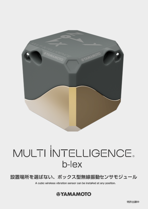
あらゆる振動をリアルタイムにモニタリングする事が可能な機器です。
25×25×25【mm】の小型サイズで、どこにでも設置が可能で、任意の箇所の振動を計測可能です。
防水機能がついているので、クーラントや水に影響される環境でも使用可能です。
本体に無線送受信機を内蔵しており、お手軽にご使用いただけます。
加速度現象の”見える化”を実現し、
最適加工条件選定・トラブル解析をサポート致します。
切削以外でもプレス、摩擦攪拌接合(FSW)、3Dプリンタなどの分析にもお使い頂けます
このカタログについて
| ドキュメント名 | MULTI INTELLIGENCE 据置型無線加速度センサb-lex |
|---|---|
| ドキュメント種別 | 製品カタログ |
| ファイルサイズ | 7.3Mb |
| 取り扱い企業 | 株式会社山本金属製作所 (この企業の取り扱いカタログ一覧) |
この企業の関連カタログ

このカタログの内容
Page1
▼ 基本仕様 / Spec
電源 / power
電源( 2パターン) ●バッテリーボックス搭載型:16340型 3.7 [V] リチウムイオン二次電池
Power (2 pattern) Battery box equipped type : 16340 type 3.7 [V] Lithium-ion secondary battery
●外部電源供給型: DC 3.3 - 5 [V]
External supply power type: DC 3.3 ‒ 5 [V]
連続使用時間 (バッテリー動作時) 50 時間程度 (無線送信サンプリングレート 200 [S/s] の時)
Continuous use time About 50 hours (when wireless sampling rate is 200 [S/s])
充電時間 最大 約2.5 時間
Charging time Max 2.5 hour
無線 / Wireless
無線送信頻度 最大 200 [S/s] ( 送信間隔 1[ms]単位で可変)
Wireless transmit frequency Max 200 [S/s] (transmit frequency is variable by 1 [ms])
使用電波周波数帯 2.4 [GHz]帯
Radio frequency 2.4 [GHz] band
通信可能距離 20 m程度(遮蔽物無し)
Communicable distance About 20 [m] or less (without shielding)
加速度センサ / Acceleration sensor
加速度検出方向 直交3方向[X, Y, Z]
Direction of acceleration detection Three orthogonal directions [X,Y,Z]
センサタイプ 圧電式加速度センサ
Sensor type Piezoelectric acceleration sensor
入力可能範囲 3~300 [m/s2]
Possible input range 3~300 [m/s2]
加速度振動量表示 実効値 [m/s2]( 積分時間 約100 [ms])
Display of acceleration value RMS value [m/s2] (integration time is approx. 100 [ms])
フィルタ特性 ローパスフィルタ 24 [kHz]( 図1)
Filter characteristics Low-pass filter 24 kHz (figure 1)
形状・その他 / Shape, other
センサモジュール 寸法 25 x 25 x 25 [mm] 質量 25 [g] 防水機能あり(IP67相当)
Direction of acceleration detection Dimension 25×25×25 [mm], mass 25 [g], with waterproof function corresponds to IP67
モジュール固定方法/マグネットまたはボルト締め
Module fixing method/magnet or bolting
バッテリーボックス 寸法 28 x 29 x 63 [mm] 質量 41 [g] 防水機能あり(IP67相当)
Battery box Dimension 28×29×63 [mm], mass 41 [g], with waterproof function corresponds to IP67
ソフトウェア Advanced Control® (詳細は別紙にて)
Soft wear Advance Control®( Please see separate sheet for details.)
図1 周波数応答特性 / Figure1 Frequency response characteristics
12 b-lex
10dB
9 -3dB b-lex
6 7dB
3 b-lex
0
100E0 1E3 10E324kHz 100E3 1E6
Frequency [Hz] 設置場所を選ばない、ボックス型無線振動センサモジュール
A cubic wireless vibration sensor can be installed at any position.
特許出願中
December
Magn i tude [ d B ]
Page2
b-lex 適応事例 / Applications
40h 以上連続稼働 適応例1: 5軸加工 インペラ仕上げ加工 / Ex1: Finish Machining of Impeller for 5 Axis Control Machining
Continuous operation for 40 hours or more
加工中の加速度と座標情報を同期取得
XYZ座標空間上に加速度をプロットすることで異常箇所の早期発見が可能
バッテリー:防水性あり 切削条件・加工パスの修正を効率的に実施
Battery: Waterproof
※座標情報はCNC通信ソフトウェアAdvanced Control®で取得可能
Accelerations and cutting positions are
acquired simultaneously.
Anomaly in cutting can rapidly be detected
by 3D plot of the accelerations.
Cutting conditions and paths can be
b-lex optimized efficiently.
※Cutting positions are acquired by
センサ設置個所: ワークに設置 communication between CNC and the
Sensing position: On the workpiece software (Advanced Control®).
b-lex:寸法25×25×25mm・防水性あり ケーブル : 100~ 5000mmまで対応可能
size25*25*25mm / Waterproof Cable : Custom-made power supply cables are from 100 to 5,000 mm in length. 適応例2: NC旋盤 突切り加工 / Ex2 :Grooving for turning
工具摩耗の進行に伴う切削抵抗と加速度の変化を調査
摩耗進行に伴い切削抵抗と加速度は上昇
▼ 外部電源供給型 / External supply power type 加速度の監視により工具寿命予測や、加工中の異常検知が可能
Measurement of the changes in cutting forces and accelerations
caused by tool wear.
Cutting forces and accelerations similarly increased as wear proceeded.
Prediction of tool life and real-time detection of anomaly in cutting
can be performed by monitoring the accelerations.
b-lex 中継器 220 4.6 230
/ Power supply cable extender ACアダプタ / AC adapter 4.4 X 方向加速度 RMS [m/s^2] 220
切削抵抗 Fx [N]
210 4.2 210
200
b-lex 4.0 190
200 3.8 180
▼ 振動の計測手法 R2=0.76 3.6 170
/ Measurement of accelerations センサ設置個所:バイトホルダ上に設置 190 3.4 160
Sensing position : On the turning tool 3.2 150
180 140
3.0 130
5-M3×0.5 2.8 120
有効深さ 4 170 2.6 110
3.2 3.3 3.4 3.5 3.6 3.7 3.8 3.9 4.0 0 10 20 30 40 50 60 70 80
移動実効値演算式 / Effective value expression X 方向加速度 RMS [m/s2 ] 加工回数 [回 ]
適応例3: 粗さ管理 / Ex3: In-process management of roughness
電源入力端子
Power input terminal 職人の目視による加工面粗さの良否判断を定量化
P.C.D.18 閾値以上の加速度では粗さ不良と判断し、再加工または工具交換を実施
裏面 / Back 閾値以下の加速度で粗さクリア
※センサ固定の際は上記M3を使用すること Skilled operators’visual determination criteria for roughness is
The M3 female threads can be used for fixing the sensor module. quantified by accelerations.
If an acceleration is over the threshold, the surface undergoes
re-machining or the tool is changed.
▼ 設置場所例 / Example of Sensing position The roughness meets the roughness requirements.
粗さ不良 粗さクリア
25×25×25【mm】のコンパクトなサイズと IP67相当の防水性を有しており、場所を選ばす設置することができます。
This sensor module has a compact size of 25 × 25 × 25 [mm] and waterproof equivalent to IP67, can be installed at any position.
20 20
b-lex 18 閾値越え X 18 閾値以内 X
16 Y 16 Y
14 ⇒粗さ不良 or 刃具欠損 Z 14 ⇒粗さクリア Z
センサ設置個所:バイトホルダ上に設置 12 12
10 10
Sensing position : On the turning tool 8 8
6 6
4 4
2 2
①:主軸部分 0 0
/ Spindle part ②:ホルダー部分 / Holder part ③:ロボットアーム部分 / Robot arm part ④:治具部分 / Jig part 0 5 0 10 0 15 0 20 0 25 0 3 0 0 35 0 4 0 0 0 5 0 10 0 15 0 20 0 25 0 3 0 0 35 0 4 0 0
時間 [s] 時間 [s]
加速度 [m/s2] 切削抵抗 Fx [N]
加速度 [m/s2]
X 方向加速度 RMS [m/s2]
切削抵抗 Fx [N]


