


28+Gbps 0.5mm ピッチ基板間コネクタ
28+Gbps 0.5mm ピッチ基板間コネクタ
● 3row or 4row 0.5mm pitch SMT array
● Number of contacts : 84pos, 224pos.
● Mating length : 2.0mm
● High density
-50 Differential pairs / linear inch (224pos.)
● Blade variation
-Differential signal blade (GSSGSSG…)
-Power & low signal blade (SSSS…)
● Large mating guide ±1.6mm
● Multiple connectors are allowed on the same PCB
● Robustness (Large retention pegs)
このカタログについて
| ドキュメント名 | IT9 シリーズ カタログ |
|---|---|
| ドキュメント種別 | 製品カタログ |
| 登録カテゴリ | |
| 取り扱い企業 | ヒロセ電機株式会社 (この企業の取り扱いカタログ一覧) |
この企業の関連カタログ


このカタログの内容
Page1
28+Gbps 0.5mm pitch Board to Board Connector
IT9 Series
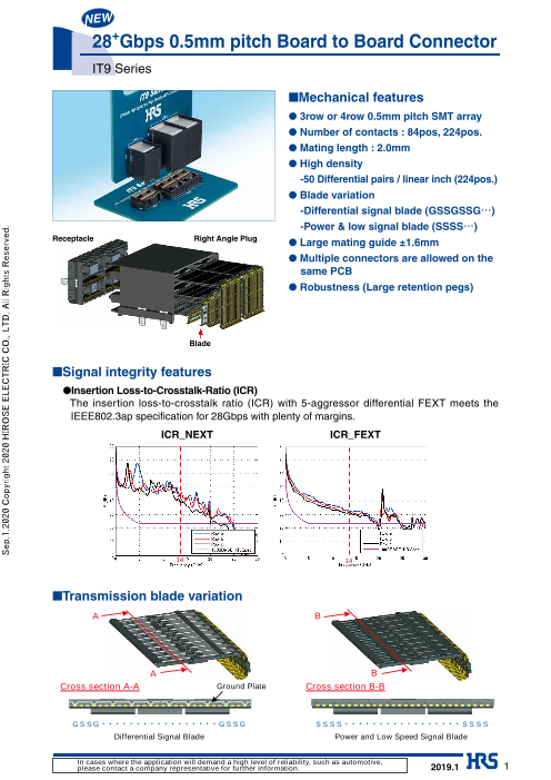
■Mechanical features
● 3row or 4row 0.5mm pitch SMT array
● Number of contacts : 84pos, 224pos.
● Mating length : 2.0mm
● High density
-50 Differential pairs / linear inch (224pos.)
● Blade variation
-Differential signal blade (GSSGSSG…)
-Power & low signal blade (SSSS…)
Receptacle Right Angle Plug
● Large mating guide ±1.6mm
● Multiple connectors are allowed on the
same PCB
● Robustness (Large retention pegs)
Blade
■Signal integrity features
● Insertion Loss-to-Crosstalk-Ratio (ICR)
The insertion loss-to-crosstalk ratio (ICR) with 5-aggressor differential FEXT meets the
IEEE802.3ap specification for 28Gbps with plenty of margins.
ICR_NEXT ICR_FEXT
14 14
■Transmission blade variation
A B
A B
Cross section A-A Ground Plate Cross section B-B
G S S G G S S G S S S S S S S S
Differential Signal Blade Power and Low Speed Signal Blade
In cases where the application will demand a high level of reliability, such as automotive,
please contact a company representative for further information. 2019.1 1
Sep.1.2020 Copyright 2020 HIROSE ELECTRIC CO., LTD. All Rights Reserved.
Page2
IT9 Series●28+Gbps 0.5mm pitch Board to Board Connector
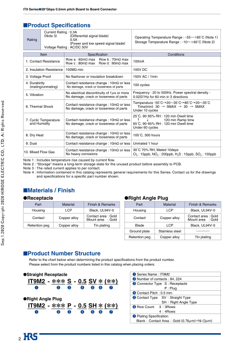
■Product Specifications
Current Rating : 0.3A
(Note 3) (Differential signal blade) Operating Temperature Range : -55~+85˚C (Note 1)
Rating 0.5A
(Power and low speed signal blade) Storage Temperature Range : -10~+60˚C (Note 2)
Voltage Rating : AC/DC 50V
Item Specification Conditions
Row a : 60mø max Row b : 70mø max
1. Contact Resistance 100mA
Row c : 80mø max Row d : 90mø max
2. Insulation Resistance 100Mø min 100V DC
3. Voltage Proof No flashover or insulation breakdown 150V AC / 1min
4. Durabirity Contact resistance change : 10mø or less
100 cycles
(mating/unmating) No damage, crack or looseness of parts
No electrical discontinuity of 1µs or more Frequency : 20 to 500Hz, Power spectral density :
5. Vibration
No damage, crack or looseness of parts 0.02G2/Hz for 60 min in 3 directions
Temperature -55˚C→20~35˚C→85˚C→20~35˚C
Contact resistance change : 10mø or less
6. Thermal Shock Time(min) 30 → 5MAX → 30 → 5MAX
No damage, crack or looseness of parts
Under 10 cycles
25˚C, 90-95% RH : 120 min Dwell time
7. Cyclic Temperature Contact resistance change : 10mø or less ↑ ↓ 120 min Ramp time
and Humidity No damage, crack or looseness of parts 65˚C, 90-95% RH : 120 min Dwell time
Under 60 cycles
Contact resistance change : 10mø or less
8. Dry Heat 105˚C, 300 hours
No damage, crack or looseness of parts
9. Dust Contact resistance change : 10mø or less Unmated 1 hour
Contact resistance change : 10mø or less 30˚C 70% RH, Mated 10days
10. Mixed Flow Gas
No heavy corrosions Cl2 : 10ppb, NO2 : 200ppb, H2S : 10ppb, SO2 : 100ppb
Note 1 : Includes temperature rise caused by current fl ow.
Note 2 : “Storage” means a long-term storage state for the unused product before assembly to PCB.
Note 3 : The rated current applies to per contact.
Note 4 : Information contained in this catalog represents general requirements for this Series. Contact us for the drawings
and specifi cations for a specifi c part number shown.
■Materials / Finish
●Receptacle ●Right Angle Plug
Part Material Finish & Remarks Part Material Finish & Remarks
Housing LCP Black, UL94V-0 Housing LCP Black, UL94V-0
Contact area : Gold Contact area : Gold
Contact Copper alloy Contact Copper alloy
Mount area : Gold Mount area : Gold
Retention peg Copper alloy Tin plating Blade LCP Black, UL94V-0
Ground plate Stainless steel ――――
Retention peg Copper alloy Tin plating
■Product Number Structure
Refer to the chart below when determining the product specifications from the product number.
Please select from the product numbers listed in this catalog when placing orders.
●Straight Receptacle ❶ Series Name : IT9M2
IT9M2 - S - 0.5 SV ( ) ❷
Number of contacts : 84, 224
*** * ** ❸ Connector Type S : Receptacle
❶ ❷ ❸ ❹ ❺ ❻ ❼ P : Plug
❹ Contact Pitch : 0.5 mm
●Right Angle Plug ❺ Contact Type SV :Straight Type
SH : Right Angle Type
IT9M2 - *** P - 0.5 SH * (**) ❻ Row Count 3 :3Rows
❶ ❷ ❸ ❹ ❺ ❻ ❼ 4: 4Rows
❼ Plating Specification
Blank : Contact Area : Gold (0.76µm)+Ni (3µm)
2
Sep.1.2020 Copyright 2020 HIROSE ELECTRIC CO., LTD. All Rights Reserved.
Page3
IT9 Series●28+Gbps 0.5mm pitch Board to Board Connector
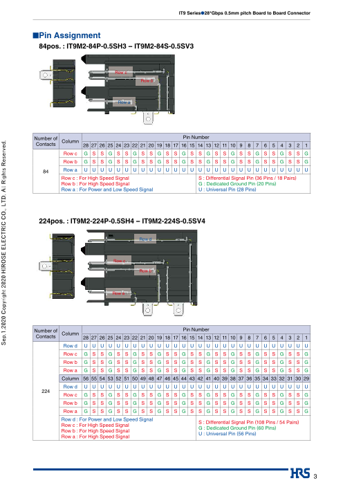
■Pin Assignment
84pos. : IT9M2-84P-0.5SH3 -- IT9M2-84S-0.5SV3
Row c
Row b
Row a
Number of Pin Number
Column
Contacts 28 27 26 25 24 23 22 21 20 19 18 17 16 15 14 13 12 11 10 9 8 7 6 5 4 3 2 1
Row c G S S G S S G S S G S S G S S G S S G S S G S S G S S G
Row b G S S G S S G S S G S S G S S G S S G S S G S S G S S G
84 Row a U U U U U U U U U U U U U U U U U U U U U U U U U U U U
Row c : For High Speed Signal S : Differential Signal Pin (36 Pins / 18 Pairs)
Row b : For High Speed Signal G : Dedicated Ground Pin (20 Pins)
Row a : For Power and Low Speed Signal U : Universal Pin (28 Pins)
224pos. : IT9M2-224P-0.5SH4 -- IT9M2-224S-0.5SV4
Row d
Row c
Row b
Row a
Number of Pin Number
Column
Contacts 28 27 26 25 24 23 22 21 20 19 18 17 16 15 14 13 12 11 10 9 8 7 6 5 4 3 2 1
Row d U U U U U U U U U U U U U U U U U U U U U U U U U U U U
Row c G S S G S S G S S G S S G S S G S S G S S G S S G S S G
Row b G S S G S S G S S G S S G S S G S S G S S G S S G S S G
Row a G S S G S S G S S G S S G S S G S S G S S G S S G S S G
Column 56 55 54 53 52 51 50 49 48 47 46 45 44 43 42 41 40 39 38 37 36 35 34 33 32 31 30 29
Row d U U U U U U U U U U U U U U U U U U U U U U U U U U U U
224
Row c G S S G S S G S S G S S G S S G S S G S S G S S G S S G
Row b G S S G S S G S S G S S G S S G S S G S S G S S G S S G
Row a G S S G S S G S S G S S G S S G S S G S S G S S G S S G
Row d : For Power and Low Speed Signal
S : Differential Signal Pin (108 Pins / 54 Pairs)
Row c : For High Speed Signal
G : Dedicated Ground Pin (60 Pins)
Row b : For High Speed Signal
U : Universal Pin (56 Pins)
Row a : For High Speed Signal
3
Sep.1.2020 Copyright 2020 HIROSE ELECTRIC CO., LTD. All Rights Reserved.
Page4
IT9 Series●28+Gbps 0.5mm pitch Board to Board Connector
■Signal Integrity
●Pin assignment
Via-Connector-via
Row a Row b Row c Row d
Power
Pair 2 Pair 4 Pair 6
Pair 1 Pair 3 Pair 5
●Insertion Loss and Return Loss
Row a
Row c
4
Sep.1.2020 Copyright 2020 HIROSE ELECTRIC CO., LTD. All Rights Reserved.
Page5
IT9 Series●28+Gbps 0.5mm pitch Board to Board Connector
●Pin assignment
Via-Connector-via
Row a Row b Row c Row d
Power
Pair 2 Pair 4 Pair 6
Pair 1 Pair 3 Pair 5
●Crosstalk
Row a
Row c
5
Sep.1.2020 Copyright 2020 HIROSE ELECTRIC CO., LTD. All Rights Reserved.
Page6
IT9 Series●28+Gbps 0.5mm pitch Board to Board Connector
●Insertion-loss-to-crosstalk ratio (ICR)
The insertion-loss-to-crosstalk ratio (ICR) with 5-aggressor meets the extrapolated IEEE 802.3ap specification to 14GHz
with plenty of margins.
Row a Row b Row c Row d
Power
Pair 2 Pair 4 Pair 6
Pair 1 Pair 3 Pair 5
NEXT FEXT
aggressors aggressors
Row a Row b Row c Row d
Power
Pair 2 Pair 4 Pair 6
Pair 1 Pair 3 Pair 5
NEXT FEXT
aggressors aggressors
6
Sep.1.2020 Copyright 2020 HIROSE ELECTRIC CO., LTD. All Rights Reserved.
Page7
IT9 Series●28+Gbps 0.5mm pitch Board to Board Connector
■Receptacle
●3row type : IT9M2-84S-0.5SV3
18.55±0.3
(0.15)
0.3±0.05 0.5 0.6 Y1
0.4 X1 0.2±0.05
2.525±0.1 0.3 X1 5.47.6
13.5 9.8
X1 2.3±0.1
17.25 Y1 0.4 Y1
c1
b1
a1
●4row type : IT9M2-224S-0.5SV4
34.05±0.3
2 0.5
0.3±0.05 0.2±0.05
2.3±0.1 0.6Y1
0.4 X1 2.525±0.1 0.3X1
29 0.4Y1
5.4
X 1 7.6
32.75 9.8
15.2
Y 1
d1
c1
b1
a1
Part No. HRS No. No. of Contacts
IT9M2-84S-0.5SV3 636-1610-0 84
IT9M2-224S-0.5SV4 636-1611-0 224
7
Sep.1.2020 Copyright 2020 HIROSE ELECTRIC CO., LTD. All Rights Reserved.
15.5±0.3
11.47±0.3
2.5±0.5
2.5±0.5
5.84±0.3
5.84±0.3
Page8
IT9 Series●28+Gbps 0.5mm pitch Board to Board Connector
■Right angle plug
●3row type : IT9M2-84P-0.5SH3
18.55±0.3
0.5
0.2±0.05
0.3X1(0.35)
0.3±0.05 2.525±0.3
0.4X1 13.5 X1
17.25
a28 a1
b28 b1
c28 c1
0.6Y1(0.8)
●4row type : IT9M2-224P-0.5SH4
34.05±0.3
2 0.5
0.2±0.05
0.3X1(0.35)
2.525±0.3
0.3±0.05 29
0.4X1 X132.75
a56 a1
b56 b1
c56 c1
d56 d1
0.6Y1(0.8)
Part No. HRS No. No. of Contacts
IT9M2-84P-0.5SH3 636-1606-0 84
IT9M2-224P-0.5SH4 636-1607-0 224
8
Sep.1.2020 Copyright 2020 HIROSE ELECTRIC CO., LTD. All Rights Reserved.
21.75±0.3 (5.53) 16.35±0.3 (5.53)
2.5±0.5 14.3±0.5
11.15 (6.2)
2.5±0.5 18.1±0.5 3.95 (6.2)
3.95
2.3±0.1
0.4 Y1
3.2
5.4
9.7
2.3±0.1 Y1
0.4 Y1
3.2
5.4
9.7
11.9
15.1
Y1
Page9
IT9 Series●28+Gbps 0.5mm pitch Board to Board Connector
■Recommended PCB Mouting Pattern
(Stencil thickness : t=0.13mm)
●Receptacle
IT9M2-84S-0.5SV3 IT9M2-224S-0.5SV4
17.25 32.75
13.5 29
X 2 X2
0.3±0.02 0.3±0.02
0.5 0.06X2 2 0.5 0.06X2
a1 a1
R0. b155 b1
5 c1
0.3
5 c1
R R0
.3
+0.2
1.1 0 (LAND) +0.1
+0.1 d1
0.7 (PTH) 0.7 0 (PTH) 0
0.1X2
0.1X2
+0.2
1.1 0 (LAND)
●Right angle plug
IT9M2-84P-0.5SH3 IT9M2-224P-0.5SH4
17.25 32.75
13.5 29
X2 X2
0.3±0.02 0.3±0.022 0.5 0.06X2
0.5 0.06X2
R0 c1.55
d1
R c1b1 0.55
b1
+0.1 a1
0.7 0 (PTH)
0.1X2
+0.2 a1
1.1 (LAND) +0.1 0 0.7 0 (PTH)
0.1X2
+0.2
1.1 0 (LAND)
Board edge
Board edge
9
Sep.1.2020 Copyright 2020 HIROSE ELECTRIC CO., LTD. All Rights Reserved.
3.45
+0.2
3.1 0 (LAND)
+0.2
3.1 0 (LAND)
+0.1 +0.1
2.7 0 (PTH) 2.7 0 (PTH)
0.1Y2 0.1Y2
(10.3) +0.11.6 0 5.4
+0.1
1.6 0 0.1Y2 7.1
0.1Y2 2.7
8.8
5.4
Y 2
8.7
Y2
10.65
3.45
+0.2
3.1 0 (LAND) +0.2
3.1 0 (LAND)
R +0.1
0. 2.7 0 (PTH)3 +0.15 0.1Y2 2.7 0 (PTH)
0.1Y2
(10.3)
+0.1
1.6 0 +0.11.6 5.40.1Y2 0
2.7 0.1Y2 7.1
5.4 8.8
8.7 14.2
11.4
Y2
14.1
Y2
.5
5
R0
5
R0
.3
Page10
IT9 Series●28+Gbps 0.5mm pitch Board to Board Connector
■Processing recommendations
●Mating Alignment Requirements
Maximum mating guidance is up to ±1.6mm in both longitudinal and lateral directions.
+/-1.6mm +/-1.6mm
Longitudinal Lateral
These values do not include the influence of misalignment in other axis nor rotation / inclination in the same time,
except for the misalignment in the single axis shown in each figure.
●Mating Angle Requirements
2.5°Max 2.5°Max
Longitudinal Lateral
10
Sep.1.2020 Copyright 2020 HIROSE ELECTRIC CO., LTD. All Rights Reserved.
Page11
IT9 Series●28+Gbps 0.5mm pitch Board to Board Connector
■Mounting Temperature Profile (Reference)
Profile Feature Condition Note
Preheat/Soak
150˚C Soak requirements should be determined by board design, oven
Temperature Min (Tsmin)
200˚C capability, and paste activation requirements.
Temperature Max (Tsmax)
60-120 seconds Caution- “oversoaking” may exhaust flux and affect soldering.
Time (ts) from (Tsmin to Tsmax)
Ramp-up rate (TL to Tp) 3˚C/second max. Other components may limit ramp rate to 2˚C/sec.
Liquidous temperature (TL) 217˚C
Shorter tL may require higher peak temperature.Time (tL) maintained above TL 60-150 seconds
Cooler peak temperatures may require longer t .
Peak package body temperature (Tp) 245˚Cmax. L
For users Tp must not exceed the classification temp (TC) of 250˚C.
Time (tp)* within 5˚C of the specified
30 seconds max.
classification temperature (Tc)
Ramp-down rate (Tp to TL) 6˚C/second max.
Package Body Exposure Limit at Adjust profile if maximum exposure limits approached or
5 seconds
Maximum Temperature exceeded.
All temperatures refer to the center of the connector body, measured on the connector body surface that is facing up
during assembly reflow. Reflow profiles in this document are based according to IPC/JEDEC J-STD-020D.1 and are for
preconditioning. Actual board assembly profiles should be developed based on specific process needs and board
designs and should not exceed the parameters in the table above.
Different solder pastes have different thermal
performance characteristics. Consult with paste
manufacturer for optimum profile setting.
11
Sep.1.2020 Copyright 2020 HIROSE ELECTRIC CO., LTD. All Rights Reserved.
Page12
IT9 Series●28+Gbps 0.5mm pitch Board to Board Connector
USA: USA: USA:
HIROSE ELECTRIC (U.S.A.), INC. HEADQUARTERS CHICAGO OFFICE HIROSE ELECTRIC (U.S.A.), INC. SAN JOSE OFFICE HIROSE ELECTRIC (U.S.A.), INC. DETROIT OFFICE (AUTOMOTIVE)
2300 Warrenville Road, Suite 150, 2841 Junction Ave, Suite 200 17197 N. Laurel Park Drive, Suite 253,
Downers Grove, IL 60515 San Jose, CA. 95134 Livonia, MI 48152
Phone : +1-630-282-6700 Phone : +1-408-253-9640 Phone : +1-734-542-9963
http://www.hirose.com/us/ Fax : +1-408-253-9641 Fax : +1-734-542-9964
http://www.hirose.com/us/ http://www.hirose.com/us/
USA: THE NETHERLANDS: GERMANY:
HIROSE ELECTRIC (U.S.A.), INC. BOSTON OFFICE HIROSE ELECTRIC EUROPE B.V. HIROSE ELECTRIC EUROPE B.V. GERMAN BRANCH
300 Brickstone Square Suite 201, Hogehillweg #8 1101 CC Amsterdam Z-O Schoenbergstr. 20, 73760 ostfildern
Andover, MA 01810 Phone : +31-20-6557460 Phone : +49-711-456002-1
Phone : +1-978-662-5255 Fax : +31-20-6557469 Fax : +49-711-456002-299
http://www.hirose.com/eu/ http://www.hirose.com/eu/
GERMANY: GERMANY: FRANCE:
HIROSE ELECTRIC EUROPE B.V. NUREMBERG OFFICE HIROSE ELECTRIC EUROPE B.V. HANOVER OFFICE HIROSE ELECTRIC EUROPE B.V. PARIS OFFICE
Neumeyerstrasse 22-26, 90411 Nurnberg Bayernstr. 3, Haus C 30855 Langenhagen, Germany 130 Avenue Joseph Kessel, Bat E, 78960
Phone : +49-911 32 68 89 63 Phone : +49-511 97 82 61 30 Voisins le Bretonneux, France
Fax : +49-911 32 68 89 69 Fax : +49-511 97 82 61 35 Phone : +33-1-85764886
http://www.hirose.com/eu/ http://www.hirose.com/eu/ Fax : +33-1-85764823
http://www.hirose.com/eu/
UNITED KINGDOM: CHINA: CHINA:
HIROSE ELECTRIC EUROPE BV (UK BRANCH) HIROSE ELECTRIC (CHINA) CO., LTD. (SHANGHAI, HEADQUARTERS) HIROSE ELECTRIC (CHINA) CO.,LTD. BEIJING BRANCH
4 Newton Court, Kelvin Drive, Knowlhill, 18, Enterprise Center Tower 2, 209# Gong He A1001, Ocean International Center, Building 56# East 4th
Milton Keynes, MK5 8NH Road, Jing’an District, Shanghai, CHINA 200070 Ring Middle Road, ChaoYang District, Beijing, 100025
Phone : +44-1908 202050 Phone : +86-21-6391-3355 Phone : +86-10-5165-9332
Fax : +44-1908 202058 Fax : +86-21-6391-3335 Fax : +86-10-5908-1381
http://www.hirose.com/eu/ http://www.hirose.com/cn/ http://www.hirose.com/cn/
CHINA: HONG KONG: TAIWAN:
HIROSE ELECTRIC (CHINA) CO., LTD. SHENZHEN BRANCH HIROSE ELECTRIC HONGKONG TRADING CO., LTD. HIROSE ELECTRIC TAIWAN CO., LTD.
Room 09-13, 19/F, Office Tower Shun Hing Square, Di Wang Commercial Centre, Room 1001, West Wing, Tsim Sha Tsui Centre, 66 103 8F, No.87, Zhengzhou Rd., Taipei
5002 Shen Nan Dong Road, Shenzhen City, Guangdong Province, 518008 Mody Road, Tsim Sha Tsui East, Kowloon, Hong Kong Phone : +886-2-2555-7377
Phone : +86-755-8207-0851 Phone : +852-2803-5338 Fax : +886-2-2555-7355
Fax : +86-755-8207-0873 Fax : +852-2591-6560 http://www.hirose.com/tw/
http://www.hirose.com/cn/ http://www.hirose.com/hk/
KOREA: SINGAPORE: INDIA:
HIROSE KOREA CO.,LTD. HIROSE ELECTRIC SINGAPORE PTE. LTD. HIROSE ELECTRIC SINGAPORE PTE. LTD. DELHI LIAISON OFFICE
143, Gongdan 1-daero, Siheung-si, 03, Anson Road, #20-01, Springleaf Tower, Office NO.552, Regus-Green Boulevard, Level5, Tower C,
Gyeonggi-do, 15084, Korea Singapore 079909 Sec62, Plot B-9A, Block B, Noida, 201301, Uttar Pradesh, India
Phone : +82-31-496-7000 Phone : +65-6324-6113 Phone : +91-12-660-8018
Fax : +82-31-496-7100 Fax : +65-6324-6123 Fax : +91-120-4804949
http://www.hirose.co.kr/ http://www.hirose.com/sg/ http://www.hirose.com/sg/
INDIA: MALAYSIA: THAILAND:
HIROSE ELECTRIC SINGAPORE PTE. LTD. BANGALORE LIAISON OFFICE PENANG REPRESENTATIVE OFFICE BANGKOK OFFICE (REPRESENTATIVE OFFICE)
Unit No-403, 4th Floor, No-84, Barton Centre, Mahatma 73-3-1, Ideal@The One, Jalan Mahsuri, Bayan Unit 4703, 47th FL., 1 Empire Tower, South Sathorn
Gandhi (MG) Road, Bangalore 560 001, Karnataka, India Lepas Penang, 11950, Malaysia Road, Yannawa, Sathorn, Bangkok 10120 Thailand
Phone : +91-80-4120 1907 Phone : +604-648-5536 Phone : +66-2-686-1255
Fax : +91-80-4120 9908 http://www.hirose.com/sg/ Fax : +66-2-686-3433
http://www.hirose.com/sg/ http://www.hirose.com/sg/
® 2-6-3,Nakagawa Chuoh,Tsuzuki-Ku,Yokohama-Shi 224-8540,JAPAN
TEL: +81-45-620-3526 Fax: +81-45-591-3726
http://www.hirose.com
http://www.hirose-connectors.com
The characteristics and the specifications contained herein are for reference purpose. Please refer to the latest customer drawings prior to use.
12 The contents of this catalog are current as of date of 01/2019. Contents are subject to change without notice for the purpose of improvements.
Sep.1.2020 Copyright 2020 HIROSE ELECTRIC CO., LTD. All Rights Reserved.