Sens●『
p
r
r
D
F
‥
‥
―
,
」
E
E
F 1眈
F
I 鰊
I
機
覺 癸燿讚 輻 悸
リードスイッチの特長 Features
小型軽量 取付面積が小さく機器装置のコンパクト化 に適 します。
Compact and Light 丁he reed switch can be mounted in a very limited space iit
is ideal for use in miniaturized equipment
完全密封 不活性ガスとともに密封されているため外部環境の影響を受けません。
Hermetica‖ y Sea:ed 丁he switching elements of the reed switch are hermetica‖ y
sealed in an inert gas atmosphere,so that they are never
exposed to the external en∨ ironment
長寿命 動作においてほとんど摺動部がないため材料疲労が少なく、機械的寿命は
Long Life 10億回以上の開閉が可能です。
丁he reed svvitCh employs no s‖ ding parts,so that there is
no fatigure related degradatlon in the quality of the materi―
als used,ensuring over b‖ ‖on times mechanicallife
高信頼性 周辺回路の設計が容易であるため、機器装置の耐久性に優れ高い信頼性を
High Reliability 発揮します。
丁he reed svvitch a‖ o lA/S eaSy designing of peripheral clrcuit
So equipment has high endurance and performs the high re―
‖ab‖ ity
リードスイッチの構造 Construction
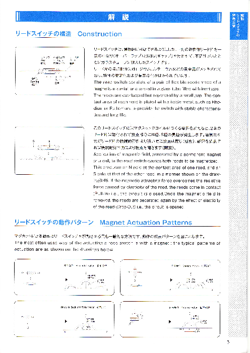
リードスイッチは、弾性的に可動できるようにした、一対の磁性体リード片を一
ギ プ ガス ーバーヤ ン 不活性 リー ド 定の重なり(オ ラツ片 プ)と 間隔 (ギヤツプ)を持たせて、不活性ガスとと
Gap lnert gas Reed
縫隙1 不活性気体 策片 もにガラスチューブに封入したスイッチです。
リード片の接点部分にはロジウム、ルテニウムなどの貴金属がメッキされて
おり、特性の安定化および長寿命化がはかられています。
The reed svvitch consists of a pair of flexible reeds made of a
magnetic material,and sealed in a glass tube f‖ led with inert gas
The reeds are overlapped but separated by a sma‖ gap The con―
tact area of each reed is plated vvith a hoble metal,such as Rho‐
dium or Ruthenium,to pro∨ ide the switch with stable characteris―
tics and long life
このリードスイッチにはマグネットやコイルのつくる磁界を加えると、2本の
リード片は磁化されて接点部分にN極、S極の異極が発生します。磁気吸引
力がリード片の機械的弾性より強い時に接点は閉じ(感動)、 磁界を消去す
れば機械的弾性力により接点を開きます (開放 )。
App‖ catio0 0f magnetic field,generated by a permanent magnet
or a co‖ ,to the reed switch causes both reeds to be magnetlzed.
This oroduces an N― pOle atthe contact area of one reed,and an
S―pole at that of the other reed,in a manner shoⅥ ノn on the dra1/v―
lng(left)lf the magnetic attracting force overcomes the resistive
force caused by elasticity of the reed,the reeds come in contact
(PU‖ ―ln)ie,the circuit is closed Once the magnetic field is
removed,the reeds are separated again by the effect of elasticity
of the reed(Drop_Out)ie,the circuit is opened
リードスイッチの動作パターン Magnet Actuation Patterns
マグネットによる動作はリードスイッチを駆動させる最も一般的な方法です。動作の代表パターンを図に示します。
丁he most often used way ofthe actuating a reed s、 Aノ itCh is with a magnet i the typical patterns of
actuation are as shown on the draⅥ 川ngs belo、 Aノ
水平動 作 HorレOnu motbn 水 平 劫 作 垂直動作 Vett cd motb∩ 垂直劫作
―×‐ Nビ IES― X ― ―×
羊 。FF領域 □
) >_諄
_に基≡_ 隆
七三三二 |1魏
′_.艦
―
主 ― _ 1/~7_′/‐、|
前後動作 Back and forth molon前 后動作 回転動作 Rotatory mOtbn 回特動作
マ~7セ > _降 Y参
0 _‐
エ
リードスイッチの種類 Reed Switch Selection
接点形式 Contact Form
A型 リー ドスイッチ (常開接点 。メーク接点 ) C型リードスイッチ (切替型・トランスフア接点 )
Form"A"(Norma‖ y Open) Forrn‖ C"(Single Pole,Double tthrow)
磁界が与えられると接点がON(閉じる)する形式です。 切替型リードスイツチで、磁界が与えられると常閉接点
S、ヘパtch contacts vvill ciose in the presence of がOFFし てから常開接点がONする形式です。
magnetic field Form‖ Cii switches have transfer mode con―
tacts VVhen magnetic field is app‖ ed,the
common contact will be transferred from nor―
ma‖ y closed(N.C.)cOntact to the norma‖ y
open(NO.)contact
接点位置 Contact Position
センタータイプ・リードスイッチ オフセンタータイプ。リードスイッチ
Center Type Reed Switch OfF Center Type Reed Switch
接点が封着ガラスの中央に位置し等しい長さのリード 小型リードスイッチに多く用いられる型で、接点が中央
片を持つています。 より封着部に片寄つています。
Svvich contacts locate in the middle of seaト Switch contacts locate in one side,near seaト
ing glass S、 AノitCh has the same lead length ingpart,丁 his type is frequently used for minia―
ture Reed Switch
接点材質 Contact Material
ロジウム(Rhodium) ルテニウム(Ruthenium)
ロジウムメッキされた接点は今日最もよい接点として ルテニウムはロジウムよりも高硬度であり、機械的磨
受け入れられています。高い融点と高硬度をもつてい 耗および発熱に強い特性を持つていますが、メッキ膜
るため微少負荷、重負荷のいずれに対しても極めて安 層を厚くできないためにあらゆる負荷での特性の安定
定した特性を示し、長寿命化がはかれます。 度という面では総合的にロジウムに劣ります。
Rhodium plated contacts are most popular ただし特に低負荷条件において優れた接点特性を発
丁hey have very stable characteristics and 揮するため、当社では接点表面にルテニウムを、下層
long life、へ/hen svvitching ioNlv level to heavy にアーク放電などの発生に強いロジウムを用いた2層
loads tthis is due to Rhodiumis high melting 接点構造のリードスイッチを開発して、微少負荷型に対
point and hlgh hardness しての長寿命化をはかつています。
Rutheniumis hardness is even greater than
that of Rhodium
Ruthenium contacts have better mechanical
wear and heat dissipation characteristics,yet
only when switching 10w loads
lrnpossible to make thicker the plate mem―
brane layer of Ruthenium contacts So com―
prehensively Ruthenium contacts inferior to
Rhodium contacts,on stab‖ ity of characteris―
tlcs vvlth various loads Because of these
characteristics ALEPH has developed a
double plated contact with Ruthenium Oxide
over Rhodium or Pa‖ adium tthese double
plated contacts have very good sllvitching
characteristics from lo、Aノ leVeito heavy loads
リードスイツチ セレクションページ
Part No RD-76A RD-18B RD-9B RD-7B品名
形 寸 法
(mm)
Dimens ons
∪nitimm(inCh)
接点形式 lA lA lA lA
Contact Form
接点位置※1
○ C C C
Contact Position
接点材質 ロジウム ルテニウム ルテニウム
ルテニウム
接 Contact Material Rhodium Ruthenium Ruthenium
Ruthenium
接点容量 Max 3W l W 5W 10W
Max Contact Rating
開閉電圧 Max 30∨DC 30∨ DC 100VDC 100VDC
占 Max Switching VOltage
小
開閉電流 Max 02A 01A 03A 05A
Max Switching Current
初期接触抵抗 Max
Max initial 200mΩ 250mΩ 200mΩ 150mΩ
Contact ResiStance
感動値 (A)X3 10-20 10-30 10-30 10-40
Pullin Value
電
開放値 (A)M in X3 3 5 3 5
気 Min Droo out∨ alue
的 耐電圧 Min×
2
100∨ DC 200∨DC 200VDC 200VDC
Min Breakdown∨ oltage
特
静電容量 Max 0 5oF 0 5pF 1 0pF 0 5pF
性 Max Contact Capacitance
絶縁抵抗 Min 109Ω 109Ω 109Ω 109Ω
lヽin lnsulation ReSiStance
共振周波数 9 5kHz 10kHz 7 2kHz 4 9kHz
Typ ResOnant Frequency
電気的寿命 (回 数 ) 107 107 5× 10⁷ 5× 10⁷
Electrical Life
(5∨ DC,10mA) (5VDC,10mA) (5VDC,10mA) (5VDC,10mA)
(Resistive loads)
標準コイル品名 N‐ 104 N-103
Test Co‖
特 長 超小型 小型 小型 汎用型
Features ∪ltra miniature Miniature Miniature General application
RD-8N RD-24B RD-24E HYR1501 HYR1555 HYR1506
0 2 7MAX ” φ285MAX
一 マ
φ25MAX ∞一
1
X
X く X
N 〓゙く
〓
一 0 一 く〓
一
一 一 ¨
N
” 寺 ¨ 一 ゛ O一 一‐‐一 ..
‐
]
一
一 ,
一
一 一
・φ
一
φ0 55
lA lA lA lA lC lA
C C C ○ ○ C
ロジウム ルテニウム ロジウム ロジウム ルテニウム ロジウム
Rhodium Ruthenium Rhodium Rhodium Ruthenium Rhodium
10W 15W 50W 20ヽハノ 3W 10W
100∨ DC DC 125∨ AC100∨ 200∨DC 100∨ DC 100VDC
200∨DC
10A (突入電流 ,OA 20A 05A 025A 05A (突入電流
3∧ ) 3A)
150mΩ 150mΩ 150mΩ 150mΩ 200mΩ 200mΩ
30-50 20-60 20-60 15-50 15-50 40-60
10 8 8 5 5 15
250VDC 300∨ DC 300∨DC 250∨DC 200∨ DC 250VDC
1 0pF 0 5pF 0 5oF 0 4oF 0 8pF 0 4pF
109Ω 109Ω 109Ω 1010Ω 109Ω 1010Ω
4 3kHz 2 2kHz 2 2kHz 3 5kHz 2 4kHz 3 0kHz
5× 10⁷ 108 l o8
(5VDC,10mA) 5× 10⁷ 5× 10⁷ (10m∨ DC,10μ A) (10m∨ DC,10μ A) 104
5× 10⁴ (5VDC.10mA) (5∨ DC.10mA) l o5 2× 10⁶ (12VDC,34Wランプ)
(12VDC,34W) (100VDC,100mA) (12∨ DC,250mA)
N-103 N‐ 102 TC-0502A
切替型
ランプ負荷用 汎用型 高容量型 高容量型 特殊負荷型
Single pole,
Forlamp loads General app cation High power High power High inrush current
double throw
9
ドライリードスイッチ セレクションページ
口
m 名 Part No HYR1559 HYR2003-1 HYR2031‐ 2
φ0 56
φ25MAX
形 寸 φ20MAⅨ法
(mm)
X X
一 く〓 ∞ く〓
Dimenslons 3 一 0 o一 崎
一 [¨
∪n timm(inch)
接点形式
lA lA lA lA
Contact Form
接点位置※1
C C C C
Contact Position
接点材質 ルテニウム ロジウム ルテニウム ルテニウム
接 Contact Material Ruthenium Rhod um Ruthenium Ruthenium
接点容量 Max
Max Contact Rating 10W 70W 5W 10W
開閉電圧 Max DC 200∨AC 100VDC 200VDC
点 Max Switching VOltage 500∨
Max珈融 rrent Q5A 07A 0 1lA 05An」8む
初期接触抵抗 Max l
Max lnitial 1 200mΩ 100mΩ 200mΩ 200mΩ
Contact Resistance l
感動値 (A)※ 3 15-50 35-60 5-15 15-50
Pullin Value
電
開放値 (A)Min※ 3 5 8 レシオ75%以 上 レシオ70%以 上
気 Min Drop Out∨ alue
的 耐電圧 Min米
2
1.500∨ DC 300VDC 150∨ DC 200∨ DC
Min Breakdown∨ o tage
特
静電容量 Max 0 4pF 0 4oF 0 6oF 040F
性 Max Contact Capacitance
絶縁抵抗 Min 1010Ω 109Ω 1010Ω 1010Ω
Min lnsulation Resistance
共振周波数 4 8kHz 2 5kHz 3 2kHz
Typ Resonant Frequency
108 107 7× 10⁷
電気的寿命 (回 数 ) DC,10μ A) A)
Electrical Life (10m∨ (10mVDC,10μ (10mVDC,10μ A)
5× 10⁶ 106 106
(Resistive ioads)
(250∨DC,10mA) (200VDC,250mA) (10∨ DC,4mA)
標準コイル品名
TC‐ 0502A
Test Coil
高耐圧型特 長 回― フ レン ャル型High breakdown 高容量型 ク ズド デイ ァ シ
Features High power Close differential
voltage
10
標準コイメレ 丁est CoiHnformation
■感動値、開放値 (アンペア)測 定用標準コイル
HYR2016 コイル品名
Test Coil No N-102 N-103 N-104 丁C-0502A
外形寸法
(mm) 「
Dimenslons
φ26MAX ∪nitimm(inCh) 丑
X
∞ く〓 コイル巻数 (± 10T)
0 一
い Number of Turns 10,000 5,000 5,000 5,000
N一
コイル線径
Wire Cauge φ007 φ007 φ005 φ008
コイル抵抗
Coil Resistance 1430Ω 670Ω 810Ω 440Ω
RD-24B RD‐ 7B RD-18B HYR1501
RD-24E RD‐ 8N RD-76A HYR1555
lA RD-9B HYR1506
HYR1559
HYR2003-1
C HYR2003-2
適用リードスイッチ HYR2016
Applicable for
回ジウム
Rhodium
25W
1,000VDC
※:注釈について Notes
10A
※lC:センターギャップ 〇:オフセンターギヤップ
CiCenter gap O:Off center gap
100mΩ
※2耐電圧規格については、感動値25A以上を基準としています。
感動値25A未満でご使用の場合はお問い合わせください。
15-70
BreakdoM/n vo tage specifications are based on Pu‖ ―in
sensitivity of 25 AT or higher Contact ALEPH forinformation
6 for sllvitches with less than 25 Att sensitivity
※3製品出荷時の公差 :±2A
2,500VDC
Tolerance before shipmenti± 2A
0 4oF
10¬ Ω
2 2kHz
2× 10⁶
(1,000VDC,10mA)
TC-0502A
高耐圧 高容量型
Vacuum,H gh Power,
H gh breakdown vo tage
■概 要
自動実装が可能な表面実装型リードスイッチで、
世界最小クラスの形状により、携帯電話等の小型機器に最適です。
丁hese reed svvitches are Surface― mounting type and
Suited for automatic mounting
■用 途
永久磁石との組み合わせにより、スイッチング機能、センサ機能等幅広い用途に利用できます。
When used in combination with a magnet,the reed switch
finds extensi∨ e application in llvhich it provider svvitchlng and sensing capab‖ ities
● 携帯電話 mobile phone
● 自動車電装機器 Car electroniCs
● OA機器 OA electoronics
● 家電機器 Home electoronics
■特 長
● 基板への自動実装 Suited for automatic mountlng
● リフロー半田付けに対応 Can be soldered uslng ref10w
● NRS-700シリーズは、ガラス管をケースでカバーしているため、特に取扱いが容易
With the NRS-701 series,its glass tube is covered with a case,making it easy to handle
■性 能
項 目 RD‐ 18B― S003 RD‐ 7B‐S002 NRS-701
接点構成 1メ ーク 1メ ーク 1メ ーク
最大開閉電力(W) 1 10 1
最大開閉電流 (A) 01 05 01
最大開閉電圧 (∨ DC) 30 100 30
耐電圧 (∨ DC) 200 200 200
動作時間 (ms)max 05 05 1
復旧日寺間(ms)ma× 005 005 01
バウンス時間(ms)max 05 05 05
使用温度範囲 (℃ ) -40~ +125 -40~+125 -40~+85
接点接触抵抗(mΩ )m ax 250 150 300
寿命例
(5VDC,10mA,抵抗負荷 1000万 回以上 5000万回以上 1000万 回以上)
重量 (mg)max 40 90 80
■形状寸法
RDシリーズ RD Series
シリーズ名 A B C D E
RD-18B― S003 125 23 14 12 2 75
RD-7B‐ S002 199 25 18 16 22 14
NRSシリーズ NRS Series 誓正王≡ ・≦|・
シリーズ A B C D E F ][二[[i≪名
NRS‐ 701 13 22 12 83 24 04
■テービング寸法/リール寸法 Example fOr Operation c,aracterisucs
テープ寸法 丁ape Dimensions . (mm)
シリーズ名 RD-18B RD-7B NRS.701
A 20 40 27
B 132 203 166
W 240 320 240
Tl Sprocよ et hole
F 115 142 11 5
E 175 175 175
G 284
Dl 155x175
Dl
Pl 80 8,0 80
P2 20 20 20
PO 40 40 40
DO 155 155 155
丁 1 03 03 04
T2 (30) (30) (32)
リール寸法 Reel Dimensions (mm)
A 250 330 330
B 100 100 80
C 130 130 130
W 245 335 245
0内寸法は参考値です
RD-18B 1,000
RD-7B 2,000
NRS-701 2.000
却
近接センサ 動作―覧 Reed Switch ttype Proximity Sensors Selection
Magnetic Actuation
マグネットの垂直、水平、前後動作による次回の変化でセンサ内部の
1/
リードスイッチをON,OFFさ せるローコスト近接センサ。
lnexpensive proxinnity sensor ⅥЛth internal reed svvitch,that /1
is turned on and off by charge of magnetic field strength
(∨ ertiCal,horizontal or longitudinal movement of magnet).
′
|
接点形式 Contact Form
N S―
①NO接点 (ノ ーマリー。オープン型)N O Contact(Nomally Open) 一
|
常開接点でマグネットが近づいた時、接点がON(閉 )状態となります。 ' OFF領域
Contact vvhich is norma‖ y open.lt wi‖ be closed when mag‐
netic field is applied
②NC接点(ノーマリークローズ型)N C Contact(nOrmally Closed)
|
常閉接点でマグネットが近づいた時接点がON(開 )状態となりますじ N S―一
Contact ⅥノhiCh is norma‖ y closed lt w‖ l be opened Ⅵノhen
magnetic field is app‖ ed.
③トランスフア接点 (切替型)Transfer contact(Form“ C")
マグネットを近づけることにより、接点が切り替わるON,OFF切 替型の出
力形式です。 一‐
Common contact(wiper)Will transfer from N C to 口‐鰤
N.O oontact when magnetic field is applied. 押^
④ラッチング接点(自己保持型)Latching Contact(Form“ D")
一度ONまたはOFFさせると、マグネットが遠のいても次の逆磁場を与
える迄の間、その接点状態を保持し続ける方式です。マグネットは水平
移動が基本です。 OFF領域
―
After being opened or closed by app‖ cation of magnetic
field,thecontact、〃‖l be held in this position(Latched)even
after removal of the magnetic fleld App‖ cation of a mag―
netic field ⅥЛth reversed polarity vv‖ l unlatch the contact
14


