


FCスタックインピーダンス測定システムをご紹介
「燃料電池インピーダンス測定システム」は、耐ノイズ性に優れた計測フロントエンドと信号処理技術により、厳しいノイズ環境下で⾼精度で安定したインピーダンス測定を実現しました。
このカタログについて
| ドキュメント名 | FCスタックインピーダンス測定システムカタログ |
|---|---|
| ドキュメント種別 | 製品カタログ |
| 登録カテゴリ | |
| 取り扱い企業 | 株式会社計測技術研究所 (この企業の取り扱いカタログ一覧) |
この企業の関連カタログ


このカタログの内容
Page1
FCスタック インピーダンス測定システム
FC stack Impedance
Measurement System
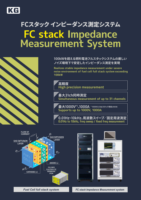
100kWを超える燃料電池フルスタックシステムの厳しい
ノイズ環境下で安定したインピーダンス測定を実現
Realizes stable impedance measurement under severe
noise environment of fuel cell full stack system exceeding
100kW
高精度
High precision measurement
最大31ch同時測定
Simultaneous measurement of up to 31 channels
最大1000V(*)、1000A * 1000V入力はスタック測定chのみ
Supports up to 1000V, 1000A
0.01Hz~10kHz、周波数スイープ/固定周波測定
0.01Hz to 10kHz, freq sweep / fixed freq measurement
Fuel Cell full stack system FC stack Impedance Measurement system
1
Page2
概 要 Overview システム例 System example
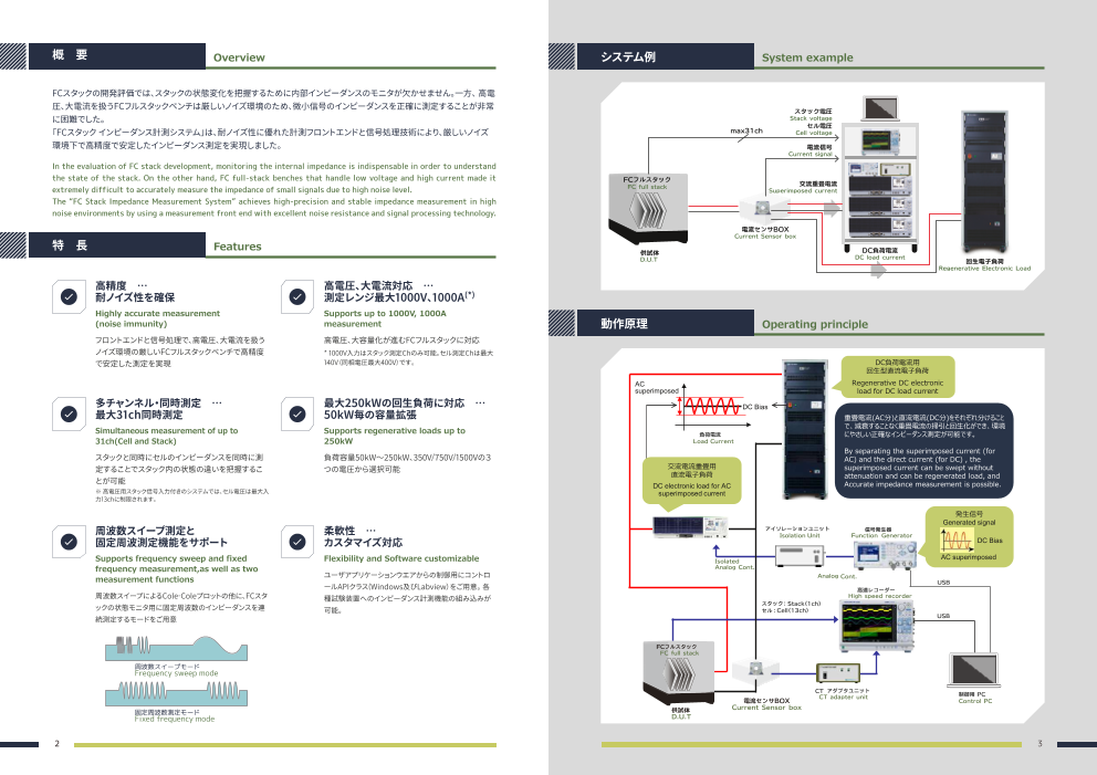
FCスタックの開発評価では、スタックの状態変化を把握するために内部インピーダンスのモニタが欠かせません。一方、 ⾼電
圧、⼤電流を扱うFCフルスタックベンチは厳しいノイズ環境のため、微小信号のインピーダンスを正確に測定することが非常
スタック電圧
に困難でした。 Stack voltage
セル電圧
「FCスタック インピーダンス計測システム」は、耐ノイズ性に優れた計測フロントエンドと信号処理技術により、厳しいノイズ max31ch Cell voltage
環境下で⾼精度で安定したインピーダンス測定を実現しました。 電流信号
Current signal
In the evaluation of FC stack development, monitoring the internal impedance is indispensable in order to understand
the state of the stack. On the other hand, FC full-stack benches that handle low voltage and high current made it FCフルスタック
extremely difficult to accurately measure the impedance of small signals due to high noise level. FC full stack 交流重畳電流
Superimposed current
The “FC Stack Impedance Measurement System” achieves high-precision and stable impedance measurement in high
noise environments by using a measurement front end with excellent noise resistance and signal processing technology.
電流センサBOX
Current Sensor box
特 長 Features
供試体 DC負荷電流
D.U.T DC load current
回生電子負荷
Regenerative Electronic Load
高精度 … 高電圧、大電流対応 …
耐ノイズ性を確保 測定レンジ最大1000V、1000A(*)
Highly accurate measurement Supports up to 1000V, 1000A
(noise immunity) measurement 動作原理 Operating principle
フロントエンドと信号処理で、⾼電圧、⼤電流を扱う ⾼電圧、⼤容量化が進むFCフルスタックに対応
ノイズ環境の厳しいFCフルスタックベンチで⾼精度 * 1000V入力はスタック測定Chのみ可能。セル測定Chは最⼤
で安定した測定を実現 140V(同相電圧最⼤400V)です。 DC負荷電流用
回生型直流電子負荷
AC Regenerative DC electronic
superimposed load for DC load current
多チャンネル・同時測定 … 最大250kWの回生負荷に対応 … DC Bias
最大31ch同時測定 50kW毎の容量拡張 重畳電流(AC分)と直流電流(DC分)をそれぞれ分けること
Simultaneous measurement of up to Supports regenerative loads up to で、減衰することなく重畳電流の掃引と回生化ができ、環境
負荷電流 にやさしい正確なインピーダンス測定が可能です。
31ch(Cell and Stack) 250kW Load Current
By separating the superimposed current (for
スタックと同時にセルのインピーダンスを同時に測 負荷容量50kW~250kW、350V/750V/1500Vの3 AC) and the direct current (for DC) , the
定することでスタック内の状態の違いを把握するこ つの電圧から選択可能 交流電流重畳用 superimposed current can be swept without
直流電子負荷 attenuation and can be regenerated load, and
とが可能 DC electronic
load for AC Accurate impedance measurement is possible.
※ ⾼電圧用スタック信号入力付きのシステムでは、セル電圧は最⼤入 superimposed current
力13chに制限されます。
発生信号
Generated signal
周波数スイープ測定と 柔軟性 … アイソレーションユニット 信号発生器
Isolation Unit Function Generator
固定周波測定機能をサポート カスタマイズ対応 DC Bia s
Supports frequency sweep and fixed Flexibility and Software customizable AC superimpose d
Isolated
frequency measurement,as well as two
Analog Cont.
measurement functions ユーザアプリケーションウエアからの制御用にコントロ Analog Cont.
USB
ールAPIクラス(Windows及びLabview)をご用意。 各 高速レコーダー
周波数スイープによるCole-Coleプロットの他に、FCスタ 種試験装置へのインピーダンス計測機能の組み込みが High speed record er
ックの状態モニタ用に固定周波数のインピーダンスを連 スタック:Stack(1ch)
可能。 セル:Cell(13ch)
続測定するモードをご用意 USB
FCフルスタック
FC full stack
周波数スイープモード
Frequency sweep mode
CT アダプタユニット
CT adapter unit 制御用 PC
電流センサBOX Control PC
固定周波数測定モード 供試体 Current Sensor box
Fixed frequency mode D.U.T
2 3
Page3
燃料電池交流インピーダンス測定 Fuel Cell AC impedance measurement 交流電流重畳用電子負荷 DC electronic load for AC superimposed current
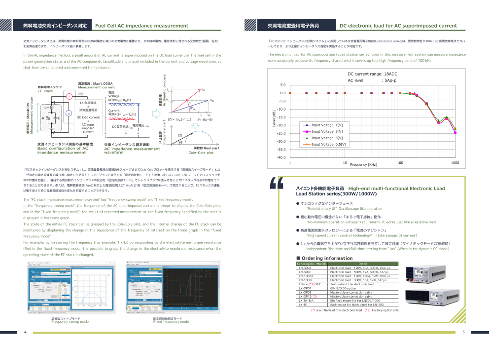
交流インピーダンス法は、発電状態の燃料電池のDC負荷電流に微小の交流電流を重畳させ、その時の電流、電圧波形に含まれる交流成分(振幅、位相) 「FCスタック インピーダンス計測システム」に採用している交流重畳用電子負荷(Load station series)は、周波数特性が100kHzと高周波帯域までカバ
を演算処理で求め、インピーダンス値に換算します。 ーしており、より正確にインピーダンス測定を実施することが可能です。
In the AC impedance method, a small amount of AC current is superimposed on the DC load current of the fuel cell in the The electronic load for AC superposition (Load station series) used in this measurement system can measure impedance
power generation state, and the AC components (amplitude and phase) included in the current and voltage waveforms at more accurately because its frequency characteristic covers up to a high frequency band of 100 kHz.
that time are calculated and converted to impedance.
DC current range: 18ADC
AC level ︓5Ap-p
測定電流:Max1,000A 5.0
燃料電 池スタック Measurement curre nt
ij i
FC stac k ac
電圧 0.0
i Voltage︓
u(t)=udc+uac(t) uj uac
DC負荷電流 Θi -5.0
Rm +
交流重畳電流 Current Θu -10.0
u 電流i(t)= idc+ iac (t) ir ur
R C DC load current -15.0
+ |Z|= |uac|/|iac| θ= ΘuーΘi
AC super -20.0 Input Voltage 1[V]
imposed DC負荷電流 i 電池電圧 udc dc
current -25.0 Input Voltage 3[V]
|Z|
Input Voltage 5[V]
θ -30.0
交流インピーダンス測定の基本 構成 交流インピーダンス測定波 形 Input Voltage 0.5[V]
Basic configuration of AC AC impedance measurem ent 実数部 Real par t -35.0
impedance measureme nt waveform Cole-Cole pl ot
-40.0
1 10 Frequency [KHz] 100 1000
「FCスタックインピーダンス計測システム」は、交流重畳電流の周波数をスイープさせてCole-Coleプロットを表示する「周波数スイープモード」とユ
ーザ指定の固定周波数で繰り返し測定した結果をトレンドグラフで表示する「固定周波数モード」を用意しました。Cole-ColeプロットでFCスタック全
体の状態を把握し、 着目する周波数のインピーダンスの変化を「固定周波数モード」でトレンドグラフに表示させことでFCスタック内部の状態をモニ
タすることができます。例えば、電解質膜抵抗(Rm)に対応した周波数(例えば1kHzなど)を「固定周波数モード」で測定することで、FCスタックの運転
状態を変えた時の電解質膜抵抗の変化を把握することができます。 ハイエンド多機能電子負荷 High-end multi-functional Electronic Load
“ Load Station series(300W/1000W)
The "FC stack impedance measurement system" has "frequency sweep mode" and "fixed frequency mode".
In the "frequency sweep mode", the frequency of the AC superimposed current is swept to display the Cole-Cole plot, ● オシロライクなインターフェース
“Revolutionary UI” Oscilloscope like operation
and in the "fixed frequency mode", the result of repeated measurement at the fixed frequency specified by the user is
displayed in the trend graph. ● 最小動作電圧の概念がない「まるで電子抵抗」動作
The state of the entire FC stack can be grasped by the Cole-Cole plot, and the internal change of the FC stack can be “No minimum operation voltage” requirement. It works just like a resistive load.
monitored by displaying the change in the impedance of the frequency of interest on the trend graph in the “fixed ● 高速電流制御テクノロジーによる「電流のマジシャン」
frequency mode” . “High speed current control technology” . [Like a magic of current]
For example, by measuring the frequency (for example, 1 kHz) corresponding to the electrolyte membrane resistance ● 1μsからの電流立ち上がり/立下り応答時間を独立して設定可能(ダイナミックモードCC動作時)
(Rm) in the fixed frequency mode, it is possible to grasp the change in the electrolyte membrane resistance when the Independent Rise time and Fall time setting from “1us” (When in the dynamic CC mode.)
operating state of the FC stack is changed.
■ Ordering information
Ordering No. (Model) Detail
LN-300A Electronic load 120V, 60A, 300W, 20A/μs
LN-300C Electronic load 500V, 12A, 300W, 1A/μs
LN-1000A Electronic load 120V, 180A, 1kW, 30A/μs
LN-1000C Electronic load 500V, 36A, 1kW, 3A/μs
LN-xxx(*1)/REC Test data of the electronic load
LX-OP01 GP-IB/DIDO option
LX-OP03 Master/slave connection cable
LX-OP12(*2) Master/slave connection cable
LX-RK-EIA EIA Rack mount kit for LN300/1000
LX-BP Rack mount kit blank panel for LN-300
(*1)xxx : Name of the electronic load (*2) Factory option only
周波数スイープモード 固定周波数測定モード
Frequency sweep mode Fixed frequency mode
4 5
測定電圧:Max400V
Measurement voltage
(-)虚数部 演算処理
Imaginary par t Arithme tic process
Level [dB]
~~ ~~ ~~
Page4
DC負荷電流用回生型直流電子負荷 Regenerative DC electronic load for DC load current ハイエンド多機能電子負荷基本仕様
High-end multi-function electronic load basic specifications
「FCスタック インピーダンス計測システム」に採用している回生型直流電子負荷(Ene-phant series)は、50kWから250kWの大容量に対応しておりま
Model LN-300A LN-300C LN-1000A LN-1000C
す。トランス絶縁方式を採用しており電力系統ノイズの影響を受けず、正確なインピーダンス測定を実施することが可能です。また回生電力ノイズは Max rate 120V, 60A, 300W 500V, 12A, 300W 120V, 180A, 1kW 500V, 36A, 1kW
ClassAに準拠しています。 回生電力ノイズにより他のデバイスに影響を与えないように設計されています。 1V @60A 3V@12A 1V@180A 3V@36A
Min operating voltage 0.5V@30A 1.5V@6A 0.5V@90A 1.5V@18A
The regenerative DC electronic load (Ene-phant series) used in the “FC stack impedance measurement system” is 0.2V@12A 0.7V@2.8A 0.2V@36A 0.7V@8.4A
compatible with large capacity from 50kW to 250kW. The transformer insulation method is adopted therefore it is Loading mode CC, CR, CV, CP, EXT, Dynamic, Short
Slew rate 20A/us 1A/us 30A/us 3A/us
possible to carry out accurate impedance measurement without being affected by system grid noise. Min response time > 500ns
Regenerative power noise conforms to Class-A. Designed so that it does not affect other devices due to regenerative 1 master unit can control multiple slave units.(Max 10 units)
Parallel operation Those loads to be in same voltage rating. (When the master is LN-300A,
power noise. then the slaves are either LN-300A or LN-1000A)
Measurement mode DCV, DCA, Power(Calculated), Ripple voltage(Option: RC-02A)
Interface USB & EXT analog input: Standard. GPIB&DIDO or LAN : Optional
■ 90% 以上の回生効率 ■回生電力ノイズ CISPR の ClassA に準拠 Trigger output 0 to 5V (Photo-coupler output)
Over 90% regenerative efficiency Conforming to CISPR Class A Current monitor output DC 0 to 5V (Not isolated)
Parallel connection(Master/Slave) 10 sets
90% 以上 (定格負荷時) と高効率を実現。 [dB(μV)] Protection & Alarm OCP, OPP, OV-alarm, Over Temp Protector and Reverse connection alarm
110 <CISPR11 Group1 Class A>
さらに定格電力の 15% 以上であれば 80% 以上の回生効率を実現。 Limit(QP) Power requirement AC85 to 264V, 50/60Hz
100 Limit(AV)
<160316_CE018_Final> Dimensions: W x H x D mm 215 × 129 × 420 430 × 129 × 450
Realized over 90% high efficiency. (at rated loading) 90 Scan(L1,PK)
QP Level-(L1) Weight Approx: 6.5kg Approx. 13kg
Regenerating efficiency of 80% is achieved for 15% or 80 C-AV Level-(L1) Note: The specifications are subject to change without prior notice.
above loading. 70
60
100
50 回生型直流電子負荷基本仕様
90 40
80 30 Regenerative DC electronic load basic specifications
LoRange100V50Hz input 20
70
10 Model NT-AD-50KO-L NT-AD-50KH-L NT-AD-50KD-L
60 LoRange200V50Hz input 0 Max rate 1500V 100A 50kW 750V 200A 50kW 350V 300A 50kW
50 0.150 0.500 1.000 5.000 10.000 30.000
Frequency [MHz]
1600 800 400
1500V 750V
40 350V
1400 700 350
1200 600 300
30 ■トランスを用いた電気絶縁を採用 Operating range 1000 500 250
20 Isolated by the transformer 50kW 50kW 50kW
800 400 200
(Power curve) 167V
600 300 150
500V 250V
10 400 200 100
200 100 50
100A
0V 33A 67A
0V 200A
0 0 0V 143A 300A
0 The load and grid are 0
0 25 50 75 100 0 50 100 150 200 250 0 50 100 150 200 250 300 350
1 2 3 4 5 6 7 8 9 10 isolated by transformer. Load current【A】 Load current【A】 Load current【A】
Load 負in荷pu入t力 p電ow力e(rk W(k)W)
NT-AA-10KE-L Lo Loading mode CC,CV,CP,CC+CV,CP+CV,MPPT
NaTd- AinAp-u1t0 -K ER-eLg負en荷er入at力iv―e回 po生w電e力r e効ff率ic特ie性ncy characteristics
Regeneration efficiency Max. 90% or over (when in rated input/output)
Ripple current 4Ap-p or less(switching freq.)
CCmode Setting / Resolution 0.0A ~ 100.0A / 0.125A 0.0A ~ 200.0A / 0.25A 0.0A ~ 300.0A / 0.3A
回生型直流電子負荷 Regenerative DC Electronic Load 250kW D CVmode Setting / Resolution 20V ~ 1500v / 2V 20V ~ 750v / 1V 20V ~ 350v / 0.5V
̃
“ Ene-phant series(50kW~250kW) CPmode Setting / Resolution 0kW ~ 50kW / 20W
3 MPPT mode Hill climbing method(factory option)
● オシロライクなインターフェース models CC+Cvmode Setting range, resolution, accuracy: Same as CC mode & CV mode
“Revolutionary UI” Oscilloscope like operation CP+Cvmode Setting range, resolution, accuracy: Same as CP mode & CV mode
Emergency stop, internal over voltage, internal over heat, over current, over voltage,
● 最大定格1500V Protection
low voltage, over power, DC side reverse connection
Supports up to 1500 V by connecting in series. Protection
System protection “Over current ,over voltage, low voltage, over frequency, low frequency,
(2 units max. *Neutral point to be connected to the earth)
function passive islanding detection, active islanding detection”
● 系統連系規定に準拠 Interface Standard RS-232C, LAN
Conforming to the grid regulation and provided over.
External DI Photo coupler input( DC12 ~ 24V/8mA)
DO Photo coupler output open collector( DC24V/10mA,1mA recommended)
● 多彩なインターフェース RS-232C,LAN,DIDO を標準装備 control AI 0 ~ 10V( CC, CC limit, CV, CV limit, CP, CP limit
RS-232C, LAN, DIDO are standard. Voltage 0 ~ 10V / 0 ~ F.S.of Voltage BNC/50 Ω /Insulated output
Monitor output
● 拡張容量最大250kW(マスタースレーブ接続5台まで) Current 0 ~ 10V / 0 ~ F.S.of Current BNC/50 Ω /Insulated output
Expanded up to 250kW can be expanded by combining five units. Parallel connection(Master/Slave) 5 sets
Input Voltage “System side input: 3-phase, 3-wire, 400 ± 40V, 50/60Hz *1
■ Ordering information Power consumption 800VA 以下
Model Description 非回生モデルもあります。(最大1000V、150kW) General Operating temp/humi 0 ~ 40℃、20 ~ 85%RH(no dew, no corrosive gas.)
NT-AD-50KO-L 1500V DC regenerative electronic load Non-regenerative models are also available
NT-AD-50KH-L 750V DC regenerative electronic load W × H × D(mm) W600 × H1977.5 × D900mm
(up to 1000V, 150kW).
NT-AD-50KD-L 350V DC regenerative electronic load Weight 950kg or Less
*1: The system voltage can be changed to 3-phase, 4-wire 380V or 400V at the time of shipment from the factory upon customer request.
6 7
Regenera回ti生ve電 p力o効w率er efficiency
Level
50kW
Load voltage【V】
Load voltage【V】
Load voltage【V】
o
C M dels
Page5
FCスタック インピーダンス計測システム基本仕様
FC stack impedance measurement system basic specifications
Classification Item Content Remarks
No. of ch 1ch
Stack voltage Max.input 1000V or 1414Vpeak
Input range 200 mV ~2000V
Signal input ( ≦ 1kHz)
Common-mode input voltage Max. 800V
In systems with high voltage
stack signal inputs, cell voltages
No. of ch Max. 31ch
Stack & Cell Voltage are limited to a maximum of 13
signal Input channels.
Input range 10mV~200V Max. input 140V(DC+AC peak)
Common-mode input voltage Max. 400V
Current Current sensor DC-CT
Signal input Detect current Max. 1000A Attenuation 1500:1/Shunt R:3 Ω
A/D resolution 16bit
Voltage, current Sampling rate Max. 1MS/s
signal measurement
functions Freq. bandwidth 300kHz
BW limit (LPF) 400Hz/4kHz/40kHz/Full
・Frequency sweep mode
Measurement mode ・Fixed freq. meas mode Fixed Freq.:Single / Two freq.
・DC measurement mode
< 19Hz: DC coupled
Freq. range 0.01Hz~10kHz
≧ 19Hz: AC coupled
Freq. setting resolution Max. 20 step / decade
10 times of setting freq over
Impedance No. of cycles 1/2/4/8cycles
1kHz.
measurement Over 1000 times of measurement
section Sampling rate
frequency.
When the AC signal level is 20%
or more of the measurement
Measurement accuracy 1%
range and a resistive load (phase
difference = 0)
Meas interval for fixed Freq. mode Within 1 second 1kHz fixed., 1ch measurement
Electronic load control for AC
AC superimposing control signal ± 10V
superposition
To be prepared by the customer
Others Emergency stop function No
when necessary
●このカタログの記載内容は、2025年2月現在のものです。 ●ご購入につきましては、最新の仕様・価格・納期をご確認ください。 ●記載されている会社名・製品名は、各社
の商標もしくは登録商標です。 ●記載の仕様・形状等は改良等により予告なしに変更されることがあります。 ●記載されている内容は、 正確な情報であるよう努めており
ますが、万が一誤り等お気づきの点ございましたら当社までお問い合わせください。
取扱代理店
パワエレ営業部
日吉事業所 〒212-0055 神奈川県川崎市幸区南加瀬4-11-1
TEL 044-223-7950 FAX 044-223-7960
⼤阪オフィス 〒564-0052 ⼤阪府吹田市広芝町10-8 江坂董友ビル2F
TEL 06-6387-1039
E-mail : PWsales@hq.keisoku.co.jp / https://www.keisoku.co.jp/pw/
● CP-0180-2502