1/9ページ
ダウンロード(1.2Mb)
4種類の偏光板を搭載した、Sony Pregius 5.1 Mピクセル モデル (IMX250MZR)
偏光イメージセンサの構造とデモソフトウエアのご案内です。
Genie Nano M2450 Polarized
センサ:Sony IMX250MZR Mono
型番:G3-GM14-M2450
解像度: 2448 x 2048
ピクセルサイズ:3.45 µm
インターフェース:GigE Vision
フレームレート:Standard: 23.8 fps TurboDrive: 34.4 fps
Bit Depth:8 bit, 12 bit
動作温度:-20—65 °C (フロントプレートで測定)
ダイナミックレンジ: 56 dB
レンズマウント:C-Mount, CS-Mount
シャッタータイプ:Global Shutter
電源:PoE or 10-36 VDC
サイズ (W x H x L): 21 x 29 x 44 mm
重量: 46 g
関連メディア
このカタログについて
| ドキュメント名 | 偏光エリアカメラ Genie Nano M2450 Polarized |
|---|---|
| ドキュメント種別 | ホワイトペーパー |
| ファイルサイズ | 1.2Mb |
| 取り扱い企業 | テレダインジャパン(テレダイン・ダルサ)株式会社 (この企業の取り扱いカタログ一覧) |
この企業の関連カタログ

このカタログの内容
Page1
Genie Nano: Polarized Sensors Software Demo、Overview、Prerequisites
Teledyne DALSA • 880 Rue McCaffrey • St-Laurent, Québec, H4T 2C7 • Canada
http://www.teledynedalsa.com/Genie-Nano
G3-AN0006 Genie Nano-Polarized Demo Application
Note
Genie Nano: Polarized Sensors Software Demo
For Nano models with P/N: G3-GM14-M2450
Overview
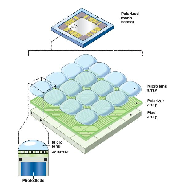
The first Genie Nano model with a quad-polarizer filter (M2450-Polarized) uses the
Sony Pregius 5.1 MP IMX250MZR monochrome sensor. These types of sensor
incorporate a nanowire polarizer filter that allows detection of both the angle and
amount of polarized light. Polarized filtering can reduce the effects of reflections and
glare from multiple directions and reveal otherwise undetectable features in the target
scene. This application note describes the implementation of a polarization demo with
several different algorithms for polarization imaging.
The Genie Nano Polarized software demo is available for download from the Teledyne
DALSA ftp server:
ftp://ftp.dalsa.com/Private/p_ProductSupport/Genie/Demo/GigeCameraDemo_Polarized.zip
Prerequisites
The following table lists the recommended Genie Nano firmware and software for this
camera model.
Genie Nano Firmware Design Software SDK
Standard Sapera LT 8.31 or higher
Sapera LT SDK (full version), the image acquisition and control SDK for Teledyne
DALSA cameras is available for download from the Teledyne DALSA website:
http://teledynedalsa.com/imaging/support/downloads/sdks/
If the required version is not available, contact your Teledyne DALSA representative.
Sapera LT includes the CamExpert application, which provides a graphical user
interface to access camera features for configuration and setup.
Doc #: G3-AN0006-V1 May 30, 2018 Page 1
Page2
Polarization Filter Theory of Operation
Polarization Filter Theory of Operation
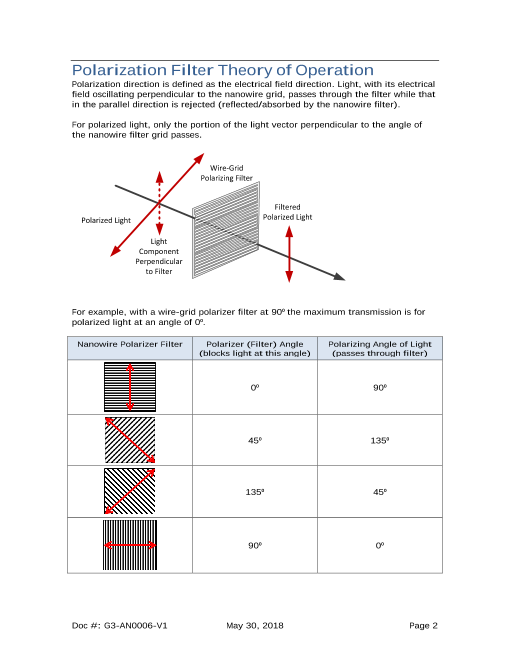
Polarization direction is defined as the electrical field direction. Light, with its electrical
field oscillating perpendicular to the nanowire grid, passes through the filter while that
in the parallel direction is rejected (reflected/absorbed by the nanowire filter).
For polarized light, only the portion of the light vector perpendicular to the angle of
the nanowire filter grid passes.
Wire-Grid
Polarizing Filter
Filtered
Polarized Light Polarized Light
Light
Component
Perpendicular
to Filter
For example, with a wire-grid polarizer filter at 90⁰ the maximum transmission is for
polarized light at an angle of 0⁰.
Nanowire Polarizer Filter Polarizer (Filter) Angle Polarizing Angle of Light
(blocks light at this angle) (passes through filter)
0⁰ 90⁰
45⁰ 135⁰
135⁰ 45⁰
90⁰ 0⁰
Doc #: G3-AN0006-V1 May 30, 2018 Page 2
Page3
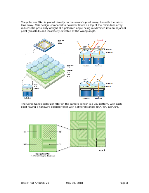
The polarizer filter is placed directly on the sensor’s pixel array, beneath the micro
lens array. This design, compared to polarizer filters on top of the micro lens array,
reduces the possibility of light at a polarized angle being misdirected into an adjacent
pixel (crosstalk) and incorrectly detected at the wrong angle.
The Genie Nano’s polarizer filter on the camera sensor is a 2x2 pattern, with each
pixel having a nanowire polarizer filter with a different angle (90⁰, 45⁰, 135⁰, 0⁰).
Doc #: G3-AN0006-V1 May 30, 2018 Page 3
Page4
The image output pattern of the monochrome camera is arranged in 2x2 pixel blocks
as follows:
X X X X ...1 2 3 4
0oY 135
o 0o 135o
1
Y2 45o 90o 45o 90o
That is, the first line output is an alternating sequence of pixels 0⁰ , 135⁰; the following
line 45⁰ ,90⁰.
Given the proportion of light available through these four filters, any angle of polarized
light can be calculated. Any given state of polarization can be composed by two
linearly polarized waves in perpendicular directions. The state of polarization is
determined by the relative ampltitude and difference in phase between the two
component waves.
Calculations on the 2x2 filter blocks result in a single pixel for each polarizer filter
angle, therefore the resulting image is one fourth the original image resolution. For
example, with an original image of 2464x2056, the resulting image is 1232x1028
(original buffer width/2 and orignal buffer height/2) for a single polarizing angle.
X
Resulting
Image
(1232x1028)
Original Image
(2486x2056)
Y
Doc #: G3-AN0006-V1 May 30, 2018 Page 4
Page5
Polarization Demo User Interface
Polarization Demo User Interface
The demo user interface can display either raw images for the image intensity sum
and each of the 4 polarizer filter angles, or when the Processing Enable checkbox is
active, the result of the 4 processing algorithms.
Raw Polorization Images
Processed Polarization Images
For display purposes, the demo applies a scale and offset to the processed images.
The range of pixel values (minimum to maximum) determines the scaling factor to
apply such that all the 8-bits (0-255) of the display are used.
Doc #: G3-AN0006-V1 May 30, 2018 Page 5
Page6
View Settings
The bottom-left area of the window groups demo parameters, such as acquisition
control, camera pixel format and displays acquisition related statistics including the
current exposure time, processing time, frame rate and the maximum frame rate. In
addition, a pseudo-color display can also be enabled.
View Settings
To open the View dialog, click the View button in the demo application window.
The View dialog groups various parameters related to the image display in the demo
window. For example, to fit the acquisition image to the display area, click the Fit to
Window button.
If the acquisition pixel depth is greater than 8-bits, the Range slider can be used to
select the bit range to display.
Doc #: G3-AN0006-V1 May 30, 2018 Page 6
Page7
Pseudo Color Display
Pseudo Color Display
When enabled, images can be displayed using a pseudo-color mapping. The demo
uses a text file containing a lookup table (LUT) of RGB values corresponding to 8-bit
grayscale values.
Doc #: G3-AN0006-V1 May 30, 2018 Page 7
Page8
Raw Polarized Images、Demo Processing of Polarized Image Data、Stokes Parameters
Raw Polarized Images
Raw, unprocessed polarized images can be extracted from the sensor for each of the
polarizer filter angles (90⁰, 45⁰, 135⁰, 0⁰) and analyzed.
For example, the raw image of a computer LCD monitor, at the polarizer filter angle
45⁰, displays a seemingly black image; since this particular LCD is designed with a
polarizer filter at this angle, it is effectively blocked. However, by adjusting the
contrast and brightness settings (for display purposes only), image details can be
revealed.
Raw Polarized Image at 45⁰ Contrast/Brightness Enhanced Image
Demo Processing of Polarized Image Data
Different algorithms can be applied to the polarized images for image processing.
The Sapera LT Polarized Sensor Demo implements the following processing
algorithms, where I is the pixel intensity and the numeral represents the angle:
• Stokes S1: S1 = 0 - I90
• Stokes S2: S2 = I45 - I135
• Angle of Polarization (AoP):
Page9
Degree of Linear Polarization (DoLP)、Angle of Polarization (AoP)、Sample Images
Degree of Linear Polarization (DoLP)
The degree of linear polarization is defined as the ratio of the intensity of the polarized
part to the total intensity. That is, it is a measure of the what percentage of the total
average lightwave signal is polarized, and can be related directly to mateial properties.
Angle of Polarization (AoP)
Angle of Polarization is the angle of the major axis of the polarization ellipse. This can
be related directly to material properties.
Sample Images
The following images of a computer LCD monitor show the effects of the various
processing algorithms.
Raw Image Intensity Summation Degree of Linear Polarization
Angle of Polarization Stokes S1
Stokes S2
Doc #: G3-AN0006-V1 May 30, 2018 Page 9


