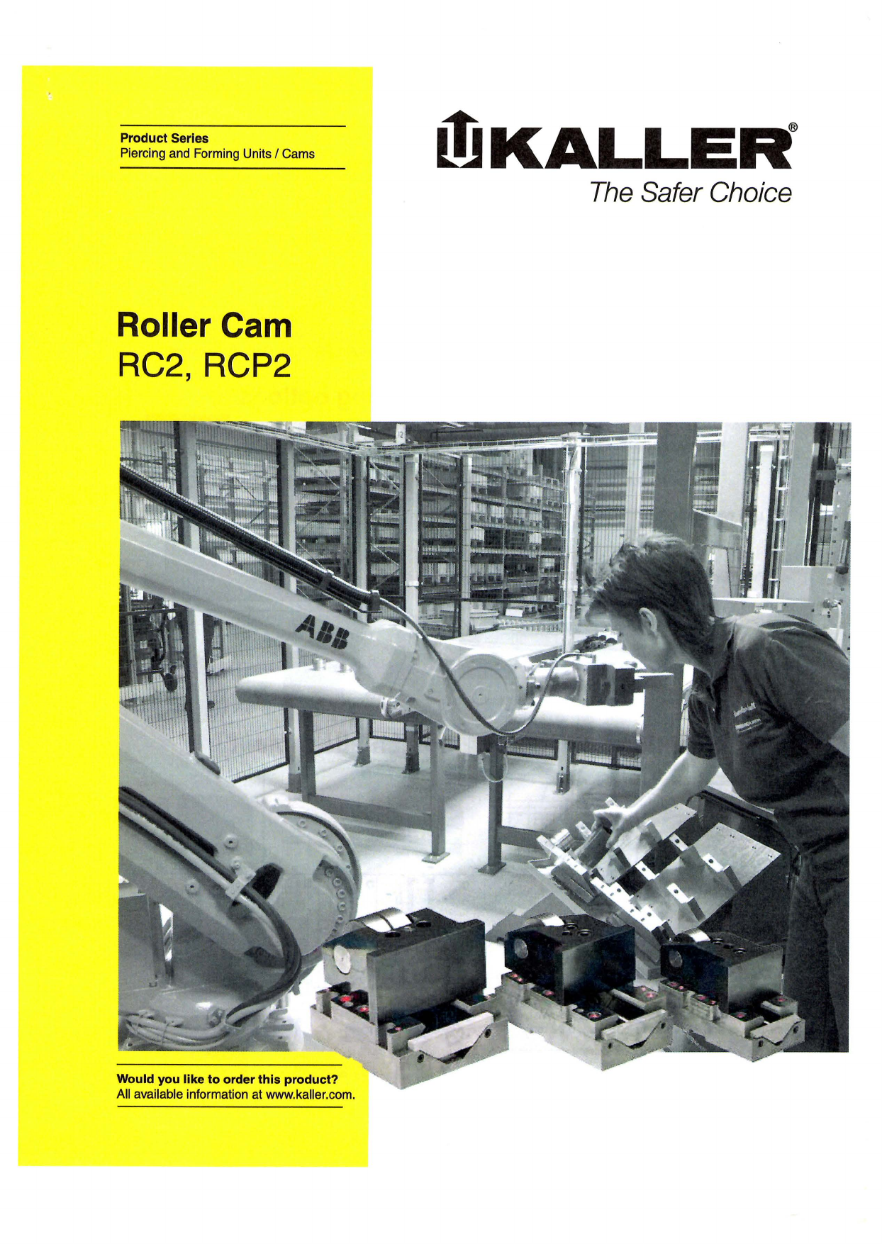
ローラー駆動式のカムユニットです。1ユニットであらゆる角度に使用可能です。 ノイズの削減にも役立ちます。ガススプリングが内蔵されており、カムの戻しを行っています。
ガススプリング内蔵の、機械式カムユニットです。
標準タイプのRCシリーズと、PSA(プジョー)標準のRCPタイプがございます。
このカタログについて
| ドキュメント名 | あらゆる角度に対応可能!静音効果もある、ローラー駆動カムユニット |
|---|---|
| ドキュメント種別 | 製品カタログ |
| ファイルサイズ | 4.2Mb |
| 登録カテゴリ | |
| 取り扱い企業 | KALLER (この企業の取り扱いカタログ一覧) |
この企業の関連カタログ

このカタログの内容
Page1
Product Series
Piercing and Forming Units IC ams 自KALLE~®
Roller Cam
RC2, RCP2
Would you like to order this product?
Al available information at www.kaller.com.
Page2
TECHNICAL FACTS IR OLLER CAM・RC2・RCP2
Roller Cam RC2 and RCP2
KALLER Roller Cam has been developed to meet the industry’si ncreasing demands on standard cam units.
This new generation offers:
-High precision and maintenance free guiding allowing
for more o行centerloading and upside-down installation
-Long service life
-Built in return stroke dampening
-Easy punch attachment. For other type of application,
please contact your local distributor or Stromsholmen AB
The KALLER Roller Cam is available for am aximum piercing force of 30 kN, 50 kN and 150 kN. The driver
itself is to be designed by the user to give the required displacement profile. The contact surface on the driver
should be hardened to approximately 58-60 HRC. Wer ecommend using KALLER Roller Cam driver plates.
Design Mounting options
Dnver
Heavy Duty Roller Bearing
Assembly Bolt
Front End
Plate
Lock Ring
Punch location Punch attachment
A IB
e一・F=O
c
Basic information
Recommended max. strokes/min ・.H-・40spm (at 20。C) G
Max.Ro ller Cam velocity….・H .・.・.H ・..0.8 mis
Max. play at face of punch unit .・H ・-…・0.02mm
Note! For information about max. attachment weight,pl ease
contact your local distributor or Striimsholmen AB
We問団刊@納eright to add,d elete or m。c附 components剛th。utnotific凶on
kaller.com 刷Idimensionsa re statedi nm m.刈ldimensionsa ren ominalun le'6 tolerance iss tated.
Page3
ROLLER CAM・RC2・RCP2IT ECHNICAL FACTS
Roller Cam- Sensor Kit Roller CamS ensor Kits are an optional accessory to all
Roller Cams, providing a signal to the press when the
Roller Cami s in start position. The Sensor Kit can easily
bea ttached to the Roller Camu sing return stop screw.
Note! For more
information, please
contact your local
distributor or
Str凸msholmenAB.
Dimensions RC2 30 & RC2 50
「一日一寸
ト
L
RC2 30 & 50
Order No. Stroke S N胃,。lnal Initial return Gas Max.wi dth
(mm) f。rce(daN) force (daN) spring A B c D F G H K L M p R x of the driver
Rq230-050 50 190 56 88
3,000 200 M2200 94 117 79 25 116 86 64 94 62 31 31
RC2 30-080 80 220 86 118
36
RC250-050 50 190
140 .~6 ~
88
103 40
RC250・080 80 5,000 350 X350 220 120 86 105 29 111 118 75 120 72 36
Rc2s0-100 国 100 240 157 126 120 158 57
Note! For 20 & 30 CAD downloads, see www.kaller.com.
Wer・servethe right lo ad, delete or modify components w刷。utnotification.
Al dimensionsare stated in mm. All dimensions are nomin創 U川estoleran国 si蜘 ted kaller.com
Page4
TECHNICAL FACTS IR OLLER CAM・RC2・RCP2
Dimensions RCP2 150
「一一?一一寸
「
L~
同コ~ T
RCP2150
Dimensions as per PSA standard
Initial Max.
N,。ninal return width
Stroke S force force Gas of the
Order No. (mm) (daN) (daN) spring A D K driver
RCP2150・050 50 200 123 47
RCP2 150-080 80 15,000 500 X500 230 153 77 62
RCP2150”100 100 250 173 97
Dimensions RCP2 30 & RCP2 50
0P
Th聞 adfor
handlingM 16
RCP2 30 & 50
Dimensions as per PSA standard A
。 Initial Max. N minal
s return Gas width
force
Stroke force spring of the
Order N.。 (daN) (mm) (daN) A B c D F G H K L M p R x driver
RCP230・050 50 190 116 46
3,000 200 M2200 100 117 82 25 116 86 64 94 62 31 31
RCP2 30・080 80 220 146 76
36
RCP250・050 50 190 116 46
RCP2 50・080.80 5,000 350 X350 220 120 140 146 102 29 111 103 76 75 120 72 40 36
RCP250・100 100 240 166 96
Note! For 20& 30C ADd ownloads, see www.kaller.com
kaller.com We reserve theri ght to add, del副eor modify comp。nentswithout nott岡i山nAl dimensions are stated inm m. Al dimensionsa re nominal unlessto lerance is stated
Page5
ROLLER CAM・RC2・RCP2IT ECHNICAL FACTS
Roller Cam- Driver Plate KALLER Roller Cam Driver Plate has been designed
to simplify the installation of Roller Cams.
• Ground and hardened contact surface (60 HRC)
・Standardizedsizes
• Independent of installation angle
Driver Plate
-Flat
Order No. A B c D E Weight [kg]
174 160 134 110 32 1.16
保(φ! 1|ゆ 3021265・02 264 250 224 200 32 2.00 J
||
c | ?|
B
Driver Plate
A -Soft Start &S top
~n i 1
円
D
Order No. A B c D E Weight [kg]
c 3021570・01 194 180 154 130 32 1.43 損咽
B | ?| 3021570・02 284 270 244 220 32 2.27
一凶
幽
3021570・03 194 180 154 130 65 2.91
A 干~ 3021570・04 284 270 244 220 65 4.61
ト-
ηc
ト-
It')
笠主主i D
Wer ese刊 ethe right to add, delete or modify components without notification.
All dimensions ares回tedin mm.A ll d1mens旧nsare nominal unless tolerance is stated kaller.com
Page6
より安全な選択
1983年lこ登場したKAL正Rの力ススプリンク按痛は、すぐに世界中で受け入れられました。より安全な選
択ートレーニング、安全性、そして信頼性ーは、常!こより安全な作業環境を提供する胤LLERの, 最優先事
項です.方ススプリングおよび刀スまた1まホースリンクシステムを選択する際には、すべてのKALLER製
品をご接討ください.
KALLERトレーニシグプログラム
トレーニング。 KALLERトレーニングプログラムは、間違いなく、安全性および信頼
性機能の重要性を理解して享受するための最高かつ最もクリエイテイブな方法です。
200万ストロークのPED承臨
轡 信頼性。 KALLERの200万ストロークのPED承認は、より安全なコンポーネントザイクル寿命を保証します。
日 フレックスガイドT”システb.I l 信頼性。ザーピス寿命を延ばし、毎分のストローク回数を上げ、ツールの水平移動の
許容範囲を広げます,
』当
デュアルシールτ同リ〉クシステム
誠 信頼性.掻動によって発生する漏れによる製造の中断を抑えます。非回転式の構造に
より、取り付けも簡単です。
喫建察
オーバーストローク保橿システム
畠 安全性。刀ススプリングがオーバーストロークとなった場合l乙ごの機能によりツー
属 ルの破損や怪我のリスクを抑えることができます。 mH
O
国 NZ山古
川
W
E
m
オーバーロード保纏システム gh
M
g
昌 安全性。力ススプリングの力が加わった力ムやツールパーツが詰まった場合はどう c亡色、也 しますか?ごの機能は、このようなリスクを抑えます。 白〈2…室」
o
z
オーバーブレ'Yシャー保謹システム mz
o
t
ル ・F切安全性。内部の方ス圧が最大許容値に達した場合!こ、スプリングから刀スを排気し @島 門て事故を防止します. 0一 ・凶山守
Ha
NO
O
回
kaller.com


