


CUTTING TOOLS PRODUCTS CATALOGUE
掲載製品
◆異形工具
◆刃先交換式工具
◆フライス切削用インサート
◆モジュラーミル専用シャンク
◆AVアーバ(防振アーバ)
◆刃先交換式工具用部品
◆詳細はカタログをダウンロードしご覧いただくか、お気軽にお問い合わせ下さい。
このカタログについて
| ドキュメント名 | 切削工具 商品カタログ 刃先交換式工具編【2025-2026】 |
|---|---|
| ドキュメント種別 | 製品カタログ |
| ファイルサイズ | 16.4Mb |
| 登録カテゴリ | |
| 取り扱い企業 | 株式会社MOLDINO (この企業の取り扱いカタログ一覧) |
この企業の関連カタログ


このカタログの内容
Page1
CUTTING TOOLS
PRODUCTS CATALOGUE
切削工具 商品カタログ
2025~2026
穴異技超形あ硬術工けエ具工ン資ド具料ミル
ね刃異先じ形交切工換り具式工工具具
面フラ取イりス工切具削用インサート
モジュラーミル専用シャンク
AVアーバ(防振アーバ)
刃先交換式工具用部品
Page2
異
異形工具 形
工
Special Shape Tools 具
高能率仕上げ加工用 異形工具(ソリッドタイプ)
High Efficiency Finishing Special Shape Tool Series (Solid type)
GS4TN………………B2
高能率仕上げ加工用 刃先交換式異形工具シリーズ
High Efficiency Finishing Indexable Special Shape Tool Series
GF1……………………B4
GF2T …………………B6
GF3L …………………B8
GP1LB ……………B10
GP1T ………………B12
環境負荷低減への配慮により、既に一部の製品についてはドライバー、ねじ焼き付け防止剤は別売りとさせて
いただいております。今後、従来品についても一部製品を除き、同梱を取りやめ、別売りとさせていただきます。
In consideration of reducing our environmental burden, we have already stopped bundling the screw driver and screw anti-seizure agent with
certain products. They will no longer be supplied with conventional products (with certain exceptions), and will instead be sold separately.
B1
Special Shape Tools
Page3
GALLEA GS4TN
GALLEA GS4TN
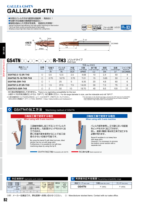
●外周のバレルR刃は勾配面を高能率 ・ 高品位に!
●先端R刃は曲面の接続面を高品位に!
●独特な強ねじれ刃形状を採用、 低抵抗化を実現!
・Barrel R achieves high-efficiency and high-quality machining for tilted section
・Tip R can finish curved connecting faces to high quality 切削
フォーム公差:±0.01
・ 条件表
Employs unique high helix shape and realizes low cutting force. Form tolerance B3
Carbide Helix angle Cutting Conditions
R2 DCX
R1 DN 15°
4枚刃 DCONMS
4 Flutes
異 LU
形 APMX LF
工
具
ソ GS4TN . - . R-TH3 ソリッドタイプ
リ Solid type
ッ
ド 寸法 Size (mm)
エ 商品コード 在庫 バレルR 外径 刃長 首下長 首径 全長 シャンク径
ン Item code 先端 R
Stock Tip R Barrel R Tool dia. Flute length Under neck length Neck dia. Overall length Shank dia.
ド R1 R2 DCX APMX LU DN LF DCONMS
ミ
ル GS4TN2.5-12.5R-TH3 ◎ 0.5 12.5 2.5 4.68 10 2.4 50 4
GS4TN3.75-18.75R-TH3 ◎ 0.75 18.75 3.75 7.01 15 3.65 50 4
GS4TN5-25R-TH3 ◎ 1 25 5 9.35 20 4.8 60 6
GS4TN7.5-37.5R-TH3 ◎ 1.5 37.5 7.5 14.03 30 7.3 75 8
GS4TN10-50R-TH3 ◎ 2 50 10 18.70 40 9.5 100 12
・本工具は再研磨対応しておりません。There is no regrinding compatibility for this tool.
・大径サイズは刃先交換式エンドミル「GP1T」をご使用ください。For the large diameter in size, use the indexable end mill "GP1T".
※工具の詳細形状についてはMOLDINOホームページよりDXFデータをダウンロードしてください。 ※For information on the detailed tool shape, download the DXF data from the MOLDINO
(MOLDINO工具選定データベースTOOL SEARCH:https://data.moldino.com/toolsearch/) Tool Engineering home page. (MOLDINO Tool Engineering tool selection database
TOOL SEARCH: https://data.moldino.com/toolsearch/)
GS4TNの加工方法 Machining method of GS4TN
5軸加工機で使用する場合 3軸加工機で使用する場合
When using with 5-axis machine When using with 3-axis machine
工具軸を傾斜し加工することでバレルR バレルR部を使用し、立ち壁に近い勾配面
部を使用し、勾配面がピッチを大きく加 をピッチを大きく加工できます。
工できます。 但し、底部(隅部)等は別工具で加工する
更に先端R部を使用することで加工段 必要が有ります。
差の少ない切削が可能です。 Barrel R enables to cut steep face
By using the barrel R with tilted tool axis, tilted with large pitch.
section can be cut with large pitch. However, it is necessary to process
Furthermore, it is possible to cut with less the bottom corner section with a
machining steps by using the tip R. separate tool.
GS4TNで加工可能 Processable with GS4TN 別工具が必要 Needs separate tool
対応被削材 App l icable work material 再研磨対応外径 範囲 Re-grinding compatibility range
炭素鋼 炭素鋼 高硬度 ステン チタン合金 銅合金 アルミ 商品コード Item code 外周 Outer dia. (mm) エンド End (mm)
合金鋼 合金鋼 Hardened steel レス鋼 耐熱合金 合金
Carbon steel Pre-hardened > 45HRC > 55HRC > 65HRC Stainless Titanium alloy Copper Aluminum
Alloy steel steel steel Heat-resistant alloy alloy GS4TN × (N/A) × (N/A)
≦ 45HRC ≦ 55HRC ≦ 65HRC alloy
○ ◎ ◎ ◎ ◎
◎印:メーカー在庫品です。弊社営業へお問い合わせください。 ◎:Manufacturer stocked items. Contact with our sales office.
B2
Page4
標準切削条件表 Recommended cutting conditions
●バレルR部 加工条件 Barrel R cutting conditions
被削材 炭素鋼・合金鋼 プリハードン鋼 焼入れ鋼 焼入れ鋼 焼入れ鋼
Work material Carbon steels, Alloy steels Pre-hardened steels Hardened steels Hardened steels Hardened steels
(<35HRC) (35~45HRC) (45~55HRC) (55~65HRC) (65~72HRC)
先端R バレルR 回転数 送り速度 ap ae 回転数 送り速度 ap ae 回転数 送り速度 ap ae 回転数 送り速度 ap ae 回転数 送り速度 ap ae
Tip R Barrel R n v f n v f n v f
R1 (mm) R2 (mm) min-1 mm/min mm mm min-1 mm/min mm mm min-1 mm/min mm mm n v f
min-1 mm/min mm mm n v f
min-1 mm/min mm mm
0.5 12.5 23,550 3,060 0.22 0.05~0.1 19,100 2,480 0.22 0.05~0.1 17,830 1,960 0.22 0.05~0.1 16,550 1,820 0.22 0.01~0.05 12,730 1,400 0.22 0.01~0.05
0.75 18.75 15,700 2,670 0.27 0.05~0.1 13,840 2,460 0.27 0.05~0.1 11,880 1,780 0.27 0.05~0.1 11,370 1,640 0.27 0.01~0.05 8,570 1,230 0.27 0.01~0.05
1 25 11,780 2,540 0.32 0.05~0.1 10,500 2,260 0.32 0.05~0.1 9,130 1,670 0.32 0.05~0.1 7,040 1,440 0.32 0.01~0.05 6,490 1,100 0.32 0.01~0.05
1.5 37.5 7,850 1,990 0.39 0.05~0.1 6,930 1,780 0.39 0.05~0.1 6,190 1,390 0.39 0.05~0.1 4,460 1,230 0.39 0.01~0.05 4,290 920 0.39 0.01~0.05
2 50 5,890 1,680 0.45 0.05~0.1 5,100 1,460 0.45 0.05~0.1 4,510 1,130 0.45 0.05~0.1 3,520 1,000 0.45 0.01~0.05 3,190 770 0.45 0.01~0.05
●先端R部 加工条件 Tip R cutting conditions
被削材 炭素鋼・合金鋼 プリハードン鋼 焼入れ鋼 焼入れ鋼 焼入れ鋼
Work material Carbon steels, Alloy steels Pre-hardened steels Hardened steels Hardened steels Hardened steels
(<35HRC) (35~45HRC) (45~55HRC) (55~65HRC) (65~72HRC)
先端R バレルR 回転数 送り速度 ap ae 回転数 送り速度 ap ae 回転数 送り速度 ap ae 回転数 送り速度 ap ae 回転数 送り速度 ap ae
Tip R Barrel R n v f n v f n v f
R1 (mm) R2 (mm) min-1 mm/min mm mm min-1 mm/min mm mm min-1 mm/min mm mm n v f n v f
min-1 mm/min mm mm min-1 mm/min mm mm
0.5 12.5 34,320 2,580 0.09 0.29 28,600 2,060 0.08 0.24 26,000 1,870 0.06 0.18 24,700 1,600 0.06 0.18 20,800 1,120 0.05 0.15
0.75 18.75 25,680 2,890 0.10 0.31 21,400 2,310 0.09 0.26 19,500 2,110 0.07 0.21 18,500 1,800 0.07 0.21 15,600 1,260 0.06 0.18
1 25 22,080 3,310 0.19 0.58 18,400 2,650 0.16 0.48 16,700 2,400 0.13 0.39 15,900 2,060 0.12 0.36 13,400 1,450 0.10 0.30
1.5 37.5 20,400 3,280 0.28 0.86 17,000 2,620 0.24 0.72 15,400 1,850 0.20 0.60 14,300 1,720 0.19 0.57 11,000 1,320 0.15 0.45
2 50 15,600 3,040 0.38 1.15 13,000 2,430 0.32 0.96 11,000 1,760 0.27 0.81 10,560 1,580 0.25 0.75 7,920 1,190 0.20 0.60
●バレルR部・先端R部 共通加工条件 Cutting conditions for using both barrel R and tip R ■バレルRと先端Rの角度範囲
Angle range of barrel R and tip R
被削材 炭素鋼・合金鋼 プリハードン鋼 焼入れ鋼 焼入れ鋼 焼入れ鋼
Work material Carbon steels, Alloy steels Pre-hardened steels Hardened steels Hardened steels Hardened steels 加工形状によって接触部がバレルR部・先端R部に
(<35HRC) (35~45HRC) (45~55HRC) (55~65HRC) (65~72HRC) 分かれます。接触する箇所をご確認頂き、各箇所に
先端R バレルR 回転数 送り速度 回転数 送り速度 回転数 送り速度 回転数 送り速度 回転数 送り速度 応じた切削条件を バレルR Barrel R
Tip R Barrel R n v f n v f n v f n v f n v f ご選定下さい。 20.364°
R1 (mm) R2 (mm) min-1 mm/min min-1 mm/min min-1 mm/min min-1 mm/min min-1 mm/min Depending on the cutting
0.5 12.5 28,940 2,820 23,850 2,270 21,920 1,920 20,630 1,710 16,770 1,260 shape, the contact section
is divided into barrel
0.75 18.75 20,690 2,780 17,620 2,390 15,690 1,950 14,940 1,720 12,090 1,250 R and tip R.
1 25 16,930 2,930 14,450 2,460 12,920 2,040 11,470 1,750 9,950 1,280 Check the contact
section and select
1.5 37.5 14,130 2,640 11,970 2,200 10,800 1,620 9,380 1,480 7,650 1,120 the appropriate 先端R Tip R
2 50 10,750 2,360 9,050 1,950 7,760 1,450 7,040 1,290 5,560 980 cutting conditions 69.636° バレルR
according to each Barrel R
※切込み (ap、ae) については上記各部の条件をご参照ください section.
For cutting depth (ap, ae), refer to the above conditions for each section. 先端R Tip R
ap値は所望のカスプハイトにより下記表より選択してください。
Determine the ap value based on the desired cusp height by selecting it from the table below.
使用工具 ■ GS4TN 工具形状について
Tool カスプハイト Cusp height (mm) 外径・バレルRの接点
About tool shape Interface between tool
商品コード バレルR diameter and barrel R
0.0001 0.0003 0.0005 0.001 0.003 0.005 GS4TNの「バレルR」は「先端R」
Item code Barrel R と「外径」を2接円弧で結んだ形 バレルR部
GS4TN2.5-12.5R-TH3 12.5 0.10 0.17 0.22 0.32 0.55 0.71 Barrel R
状になっています。
GS4TN3.75-18.75R-TH3 18.75 0.12 0.21 0.27 0.39 0.67 0.87 右図をご確認ください。 先端R 外径 首径
GS4TN5-25R-TH3 25 0.14 0.24 0.32 0.45 0.77 1.00 "Barrel R" of GS4TN has a shape Tip R Tool Neck
that connects "tip R" and dia. dia.
"tool diameter" with double arc.
GS4TN7.5-37.5R-TH3 37.5 0.17 0.30 0.39 0.55 0.95 1.22 See the figure on the right. 先端R・バレルRの接点
GS4TN10-50R-TH3 50 0.20 0.35 0.45 0.63 1.10 1.41 Interface between tip R and barrel R
【注意】 【Note】
①被削材、加工形状に合わせて、適切なクーラントを使用してください。 ①Use the appropriate coolant for the work material and machining shape.
②できるだけ高剛性、高精度の機械をご使用ください ②Use a machine having as high rigidity and high accuracy as possible.
③この切削条件表は切削条件の目安を示すものです。実際の加工では加工形状、目的、 ③These conditions are for general guidance; in actual machining conditions adjust
使用機械等により条件を調整してください。 the parameters according to your actual machine and work-piece conditions.
④If the rpm of the machine is low, lower the feed rate also to put the rpm and feed
④機械の回転数が足りない場合は、回転数と送り速度を同じ比率で下げてください。 rate in the same ratio.
B3
Special Shape Tools Solid End Mills
Page5
GALLEA GF1
GALLEA GF1 動画公開中
●仕上げ加工時間短縮に新提案。
●等高線Zピッチを大きく設定できる 切削
・A new proposal for reducing finishing time. 条件表
・ B5
Contour Z pitch can be set to larger values.
Finishing Side Cutting Cutting Conditions
は数字、 は英文字が入ります。 Numeric figure in a circle and Alphabetical character comes in a square
GF1 20 M- -M モジュラータイプ モジュラーミル用シャンクはD2頁を、締め付けトルクについてはD5頁を参照ください。
Modular type Refer page D2 about the shanks for Modular Mill, Refer page D5 about tightening torque
LF L2 LF L2 DRVS(切欠部幅)
L1 THSZMS L1 THSZMS
異
形
工
具 APMX APMX
ベーシックタイプ Basic type オフセットタイプ Offset type
刃
先 在庫 刃数 希望小売
タイプ 商品コード 寸法 Size (mm) 使用インサート
交 Type Item code Stock No.of 価格(円)
flutes DCX LF APMX DCONMS THSZMS DHUB L1 L2 DRVS Insert Suggested
換 retail price(¥)
式 GF1G2016M-2-M8 ● 2 16 25 9.5 8.5 M8 14 5.5 17 10 40,650
工
具 ベーシック GF1G2020M-3-M10 ● 3 20 30 9.5 10.5 M10 17.8 5.5 19 15
タイプ XPHW0903R-20 52,410
Basic type ※1GF1G2025M-4-M10 ● 4 25 30 9.5 10.5 M10 17.8 5.5 19 15 XPHW0903R-30 63,230
GF1G2025M-4-M12 ● 4 25 35 9.5 12.5 M12 22.5 5.5 22 17 63,230
オフセット GF1T2016M-2-M8 ● 2 16 25 9.5 8.5 M8 14 5.5 17 10 40,650
タイプ GF1T2020M-3-M10 ● 3 20 30 9.5 10.5 M10 17.8 5.5 19 15 YPHW0903R-20
YPHW0903R-30 52,410
Offset type GF1T2025M-4-M12 ● 4 25 35 9.5 12.5 M12 22.5 5.5 22 17 63,230
【注意】※1と超硬シャンクをセットで使用すると干渉がありません。
モジュラーミル及び専用シャンク、専用アーバの「工具端面」「モジュラーネジ部」にグリースなどの潤滑剤は塗布しないでください。
【Note】When ※1 and carbide shank are used together as a set, there is no interference.
Do not apply lubricants such as grease, etc. to the “contact faces” and “modular screws” of the “modular mill”, “dedicated shanks” and “dedicated arbor”.
※工具の詳細形状についてはMOLDINOホームページよりDXFデータをダウンロードしてください。(MOLDINO工具選定データベースTOOL SEARCH: https://data.moldino.com/toolsearch/)
※For information on the detailed tool shape, download the DXF data from the MOLDINO Tool Engineering home page. (MOLDINO Tool Engineering tool selection database TOOL SEARCH: https://data.moldino.com/toolsearch/)
■インサート Inserts
ベーシックタイプ Basic type P 炭素鋼・合金鋼 Carbon steels, Alloy steels
:一般切削・第一推奨
M SUS等 SUS, etc. General cutting, First recommended
K FC・FCD Cast irons :一般切削・第二推奨
H General cutting, Second recommended
9.5 3 高硬度材 Hardened steels
XPHW0903R- タイプ 商品コード 精度 寸法 Size(㎜)
PN215 TH315 希望小売価格(円)
Type Item code Tolerance Suggested retail price(¥)
オフセットタイプ Offset type class R
ベーシックタイプ XPHW0903R-20 ● ● 20 1,580
Basic type XPHW0903R-30 ● ● 30 1,580
H
オフセットタイプ YPHW0903R-20 ● ● 20 1,580
9.5 3
YPHW0903R- Offset type YPHW0903R-30 ● ● 30 1,580
※工具の詳細形状についてはMOLDINOホームページよりDXFデータをダウンロードしてください。(MOLDINO工具選定データベースTOOL SEARCH: https://data.moldino.com/toolsearch/)
※For information on the detailed tool shape, download the DXF data from the MOLDINO Tool Engineering home page. (MOLDINO Tool Engineering tool selection database TOOL SEARCH: https://data.moldino.com/toolsearch/)
■部品番号 Parts
クランプねじ ドライバー ねじ焼き付き防止剤
Clamp screw Screw driver Screw anti-seizure agent
形状
Shape
適用カッタ 締付けトルク希望小売価格(円) 希望小売価格(円) 希望小売価格(円)
Fastening torque
Cutter body Suggested Suggested Suggested
(N・m) retail price( ¥) retail price( ¥) retail price( ¥)
GF1 20 M- -M 250-141 1.1 960 104-T8 1,980 P-37 1,120
【注意】クランプねじは消耗品です。使用環境により交換寿命は変化しますので早めの交換をお願い致します。
【Note】The clamp screw is a consumable part. Since replacement life depends on the use environment, it is recommended that it be replaced at an early stage.
●印:標準在庫品です。 ●:Stocked items.
B4
R
R
5.89 5.68
11° 11°
DCX
DCON MS
DHUB
DCX
DCON MS
DHUB
Page6
標準切削条件表 Recommended cutting conditions
※赤字は第一推奨材種です。Red indicates primary recommended grade.
ap値は所望のカスプハイトにより下記表より選択または下記計算式
被削材 推奨材種 切削条件
Work material Recommended Cutting condition φ16 φ20 φ25 より算出してください
grade
Determine the ap value based on the desired cusp height by selecting it from
n (min-1) 11,950 9,560 7,650
炭素鋼 the table below or by calculating it using the equation below.
vc (m/min)
Carbon steels 600 600 600
※
合金鋼 vf (mm/min)
PN215 4,780 5,740 6,120 インサート カスプハイト (mm)
Alloy steels fz(mm/t) 0.2 0.2 0.2 Insert Cusp height
( <30HRC) ap (mm) 右表を参照ください。Refer
right table 商品コード
ae (mm) ~0.1 ~0.1 ~0.1 Item code R 0.001 0.002 0.003 0.004 0.005 0.01
n (min-1) 7,970 6,370 5,100
炭素鋼 XPHW0903R-20 20 0.4 0.57 0.69 0.8 0.89 1.26
vc (m/min)
Carbon steels 400 400 400
合金鋼 PN215 XPHW0903R-30 30 0.49 0.69 0.85 0.98 1.1 1.55
vf (mm/min) 3,190 3,830 4,080
Alloy steels TH315 fz(mm/t) 0.2 0.2 0.2 H
(30~45HRC) ap (mm) 右表を参照ください。Refer
right table ap= 2 (R2-(R-H)2)
ae (mm) ~0.1 ~0.1 ~0.1
n (min-1) 9,960 7,970 6,370 R:工具R H:カスプハイト
Tool R Cusp height ap
vc (m/min)
ステンレス鋼 500 500 500
vf (mm/min)
Stainless steels PN215 3,990 4,790 5,100 R
SUS fz(mm/t) 0.2 0.2 0.2
ap (mm) 右表を参照ください。Refer
right table
ae (mm) ~0.1 ~0.1 ~0.1
n (min-1) 11,950 9,560 7,650 ※突き出し長さ3DCX以上の場合は、左記の表をもとに下記表を
鋳鉄 vc (m/min) 600 600 600 参考に調整してください。
Cast irons TH315 vf (mm/min) 5,980 7,170 7,650 When overhang length is 3DCX or greater, adjust the values shown in
FC PN215 fz(mm/t) 0.25 0.25 0.25 the table at left according to the table below.
FCD ap (mm) 右表を参照ください。Refer
right table 突き出し比率
Overhang ratio vc (m/min) vf (mm/min)
ae (mm) ~0.1 ~0.1 ~0.1
n (min-1) 4,980 3,990 3,190 <3DCX 100% 100%
vc (m/min) 250 250 250
焼入れ鋼 3DCX~ 5DCX 70% 70%
TH315 vf (mm/min)
Hardened steels 1,500 1,800 1,920
(45~55HRC) PN215 5DCX~ 6DCX 60% 60%
fz(mm/t) 0.15 0.15 0.15
ap (mm) 右表を参照ください。Refer 6DCX~ 7DCX 50% 50%
right table
ae (mm) ~0.08 ~0.08 ~0.08 7DCX~ 45% 45%
【注意】①被削材、加工形状に合わせて、適切なクーラントを使用してください。
②この切削条件表は切削条件の目安を示すものです。実際の加工では加工形状、目的、使用機械等により条件を調整してください。
③切りくず噛み込みによる工具損傷防止のため、必ずエアーブロー等による切りくず除去を行ってください。
④インサートの交換は早めに行い、過度の使用による破損を防止してください。
【Note】①Use the appropriate coolant for the work material and machining shape.
②These conditions are for general guidance; in actual machining conditions adjust the parameters according to your actual machine and
work-piece conditions.
③To prevent tool breakage due to chips clogging tool flutes, always be sure to use an air blower, etc. to remove chips.
④Ensure to index the insert at the correct time to ensure safety of the tool-body.
プログラム上の刃先形状定義 Flute tip shape definitions for programing
工具最 インサートと工具径の組み合わせにより回転軌跡形状が異なります。下記表を参照ください。
To 大
ol 傾
ma 斜
xim 角 工具最
To 大
um ol 傾
ma 斜
xim 角 Rotation locus shape will be different depending on the combination of insert and tool diameter. Refer to the table below.
in
θ clination ang u
le m incli
θ nation angle
ベーシックタイプ Basic type オフセットタイプ Offset type
インサート型番
Insert item code XPHW0903R-20 XPHW0903R-30 YPHW0903R-20 YPHW0903R-30
工具径 DCX (mm)
R R Tool dia. φ16 φ20 φ25 φ16 φ20 φ25 φ16 φ20 φ25 φ16 φ20 φ25
R (mm) 20.14 20 19.93 30.38 30 29.82 20.18 20 19.91 30.33 30 29.81
Rh (mm) 4.75 4.75 4.75 4.75 4.75 4.75 7.25 7.25 7.25 7.25 7.25 7.25
工具径DCX 工具径DCX RE (mm) 0.8 0.8 0.8 0.8 0.8 0.8 0.8 0.8 0.8 0.8 0.8 0.8
Tool dia. Tool dia. A (mm) 9.5 9.5 9.5 9.5 9.5 9.5 9.5 9.5 9.5 9.5 9.5 9.5
ベーシックタイプ オフセットタイプ
Basic type Offset type θ 11° 11° 11° 7° 7° 7° 19° 19° 19° 12° 12° 12°
【注意】小数点第三位以下を四捨五入した数値です。パラメトリックで形状定義する場合はDXFデータより必要
寸法をご確認ください。
【Note】The numbers after the third decimal point are rounded off. When defining the shape parametrically, check the required
dimensions from the DXF data.
B5
RE
Rh
R中心高さ
R center height
A
RE
Rh
R中心高さ
R center height
A
Special Shape Tools Indexable Tools
RE
RE
Page7
GALLEA GF2T
GALLEA GF2T
●高能率な傾斜壁面の仕上げ加工 ! ボールエンドミル、 ラジアスエンドミルに比べ大ピッチで加工可能です。
●大径側にシリーズ展開しました !
●経済的な2コーナ仕様 ! ユニークなインサート拘束面により2コーナ仕様を実現しました。
・High-performance tilted wall finishing! Enables machining at a larger pitch than ball end mills or radius end mills. 切削
・Series expansion toward larger diameters 条件表
・Economical 2-corner specification. Unique insert holding surface enables realization of 2-corner specification B7
Finishing Side Cutting Cutting Conditions
は数字、 は英文字が入ります。 Numeric figure in a circle and Alphabetical character comes in a square
GF2T 30 M- モジュラータイプ モジュラーミル用シャンクはD2頁を、締め付けトルクについてはD5頁を参照ください。
Modular type Refer page D2 about the shanks for Modular Mill, Refer page D5 about tightening torque
異 LF L2
形 LF L2 L1 DRVS(切欠部幅)
工 THSZMS THSZMS
具 L1
刃
先
交 12
換 φ20, φ25 12 φ35, φ40
式
工 希望小売
タイプ 商品コード 在庫 刃数 寸法 Size (mm)
具 Item cod o. of 使用インサート 価格(円)
Type e Stock N
flutes DCX LF DCONMS THSZMS DHUB L1 L2 DRVS Insert Suggested
retail price(¥)
GF2T3020M-3 ● 3 20 30 10.5 M10 17.8 5.5 19 15 52,410
オフセット GF2T3025M-4 ● 4 25 35 12.5 M12 22.5 5.5 22 17
YPHW1203R-30 63,230
タイプ
Offset type ※1GF2T3035M-5 ● 5 35 40 17 M16 28.8 6 23 22 75,630
※1GF2T3040M-6 ● 6 40 40 17 M16 28.8 6 23 22 87,250
【注意】※1と超硬シャンクをセットで使用すると干渉がありません。
モジュラーミル及び専用シャンク、専用アーバの「工具端面」「モジュラーネジ部」にグリースなどの潤滑剤は塗布しないでください。
【Note】When ※1 and carbide shank are used together as a set, there is no interference.
Do not apply lubricants such as grease, etc. to the “contact faces” and “modular screws” of the “modular mill”, “dedicated shanks” and “dedicated arbor”.
※工具の詳細形状についてはMOLDINOホームページよりDXFデータをダウンロードしてください。(MOLDINO工具選定データベースTOOL SEARCH: https://data.moldino.com/toolsearch/)
※For information on the detailed tool shape, download the DXF data from the MOLDINO Tool Engineering home page. (MOLDINO Tool Engineering tool selection database TOOL SEARCH: https://data.moldino.com/toolsearch/)
■インサート Inserts
炭素鋼・合金鋼 :一般切削・第一推奨
SUS等
FC・FCD :一般切削・第二推奨
高硬度材
商品コード 精度 材種 寸法 (㎜) 希望小売価格(円)
PN215 TH315 R ¥
YPHW1203R-30 H ● ● 30 2,120
※工具の詳細形状についてはMOLDINOホームページよりDXFデータをダウンロードしてください。(MOLDINO工具選定データベースTOOL SEARCH: https://data.moldino.com/toolsearch/)
※
■部品番号 Parts
は数字が入ります。 Numeric figure in a circle
クランプねじ ドライバー ねじ焼き付き防止剤
Clamp screw Screw driver Screw anti-seizure agent
形状
Shape
適用カッタ 締付けトルク希望小売価格(円) 希望小売価格(円) 希望小売価格(円)
Fastening torque
Cutter body Suggested Suggested Suggested
(N・m) retail price( ¥) retail price( ¥) retail price( ¥)
GF2T30 M- 265-143 2.0 960 104-T10 2,120 P-37 1,120
【注意】クランプねじは消耗品です。使用環境により交換寿命は変化しますので早めの交換をお願い致します。
【Note】The clamp screw is a consumable part. Since replacement life depends on the use environment, it is recommended that it be replaced at an early stage.
●印:標準在庫品です。 ●:Stocked items.
B6
φ
DCX
DCON MS
DHUB
DCX
DCONMS
DHUB
Page8
標準切削条件表 Recommended cutting conditions
※赤字は第一推奨材種です。Red indicates primary recommended grade.
被削材 推奨材種 切削条件 ap値は所望のカスプハイトにより下記表より選択または下記
Work material Recommended Cutting φ20 φ25 φ35 φ40 計算式より算出してください
grade conditions Determine the ap value based on the desired cusp height by selecting it from
the table below or by calculating it using the equation below.
n (min-1) 9,560 7,650 5,460 4,780
炭素鋼 vc (m/min) 600 600 600 600 インサート Insert カスプハイト Cusp height (mm)
合金鋼 v 商品コード
f (mm/min) 5,740 6,120 5,460 5,740 0.002 0.003 0.004 0.005 0.01
Item code R 0.001
Carbon steels PN215
Alloy steels fz(mm/t) 0.2 0.2 0.2 0.2 YPHW1203R-30 30 0.49 0.69 0.85 0.98 1.1 1.55
(<30HRC) ap (mm) 右表を参照ください。Refer to the
table at right. H
ae (mm) <0.1 <0.1 <0.1 <0.1 ap= 2 (R2-(R-H)2)
n (min-1) 6,370 5,100 3,640 3,190
炭素鋼 R:工具R H:カスプハイト ap
vc (m/min) 400 400 400 400 R : Tool R H : Cusp height
合金鋼 PN215 vf (mm/min) 3,830 4,080 3,640 3,830 R
Carbon steels
Alloy steels TH315 fz(mm/t) 0.2 0.2 0.2 0.2
(30~45HRC) ap (mm) 右表を参照ください。Refer to the
table at right.
※突き出し長さ3DCX以上の場合は、左記の表をもとに下記表を参考
ae (mm) <0.1 <0.1 <0.1 <0.1 に調整してください。
n (min-1) 7,970 6,370 4,550 3,990 When overhang length is 3DCX or more, adjust the values shown in the table at left
according to the table below.
vc (m/min) 500 500 500 500
ステンレス鋼 突き出し比率 O verh ang
ratio vc (m/min) vf (mm/min)
vf (mm/min) 4,790 5,100 4,550 4,790
Stainless steels PN215 <3DCX 100% 100%
SUS fz(mm/t) 0.2 0.2 0.2 0.2 3DCX~ 5DCX 70% 70%
ap (mm) 右表を参照ください。Refer to the
table at right. 5DCX~ 6DCX 60% 60%
ae (mm) <0.1 <0.1 <0.1 <0.1 6DCX~ 7DCX 50% 50%
n (min-1) 9,560 7,650 5,460 4,780 7DCX~ 45% 45%
鋳鉄 vc (m/min) 600 600 600 600 【注意】
Cast irons TH315 vf (mm/min) 7,170 7,650 6,830 7,170 ①被削材、加工形状に合わせて、適切なクーラントを使用してください。
FC PN215 fz(mm/t) 0.25 0.25 0.25 0.25 ②この切削条件表は切削条件の目安を示すものです。実際の加工では加工
FCD 形状、目的、使用機械等により条件を調整してください。
ap (mm) 右表を参照ください。Refer to the
table at right. ③切りくず噛み込みによる工具損傷防止のため、必ずエアーブロー等によ
る切りくず除去を行ってください。
ae (mm) <0.1 <0.1 <0.1 <0.1 ④インサートの交換は早めに行い、過度の使用による破損を防止してくだ
n (min-1) 3,990 3,190 2,280 2,000 さい。
vc (m/min) 250 250 250 250 【Note】
焼入れ鋼 ①Use the appropriate coolant for the work material and machining shape.
TH315 vf (mm/min) 1,800 1,920 1,710 1,800 ②These conditions are for general guidance; in actual machining conditions
Hardened steels adjust the parameters according to your actual machine and work-piece
conditions.
(45~55HRC) PN215 fz(mm/t) 0.15 0.15 0.15 0.15 ③To prevent tool breakage due to chips clogging tool flutes, always be sure to
ap (mm) 右表を参照ください。Refer to the use an air blower, etc. to remove chips.
table at right. ④Ensure to index the insert at the correct time to ensure safety of the tool-body.
ae (mm) <0.08 <0.08 <0.08 <0.08
プログラム上の刃先形状定義 Flute tip shape definitions for programing
工具最
To 大
ol 傾 インサートと工具径の組み合わせにより回転軌跡形状が異なります。下記表を参照ください。
ma 斜
xim 角
um in Rotation locus shape will be different depending on the combination of insert and tool diameter. Refer to the table below.
cli
θ nation angle
オフセットタイプ Offset type
インサート型番 Insert item code YPHW1203-R30
R 工具径 Tool dia. DCX (mm) φ20 φ25 φ35 φ40
R (mm) 30.24 30 29.84 29.78
Rh (mm) 7.92 8 8 8
工具径DCX
Tool dia. θ 14.9° 15° 15.2° 15.3°
オフセットタイプ Offset type 【注意】小数点第三位以下を四捨五入した数値です。パラメトリックで形状定義する場合はDXFデータより
必要寸法をご確認ください。
【Note】The numbers after the third decimal point are rounded off. When defining the shape parametrically, check the
required dimensions from the DXF data.
B7
RE0.2
Rh
R中心高さ
R center
height
12
Special Shape Tools Indexable Tools
RE0.2
Page9
GALLEA GF3L
GALLEA GF3L
● GF3Lは緩曲面 ・ 緩斜面の中仕上~仕上加工用途のレンズ工具です。
● GALLEA シリーズ(GF3LとGP1LB)を合わせて使用することで中仕上げ~仕上げ加工の高能率化が図れます。
● 経済的な3コーナ仕様インサートを採用
・Lens tool for semi-finishing to finishing machining on gentle curved surfaces and gentle sloped surfeces. 切削
・Using GALLEA series together it is possible to process from semi-finishing to finishing with high efficiency 条件表 B9
・Economical three corner specification insert tip Finishing Cutting Conditions
は数字が入ります。 Numeric figure in a circle
GF3L M-3-M モジュラータイプ モジュラーミル用シャンクはD2頁を、締め付けトルクについてはD5頁を参照ください。
Modular type Refer page D2 about the shanks for Modular Mill, Refer page D5 about tightening torque
LF DRVS(切欠部幅)
THSZMS
異
形
工
具
L1
L1
刃
先 商品コード 在庫 刃数 寸法 Size (mm) 使用インサート 希望小売価格(円)
交 Item code Stock No. of
fl Insert Suggested
utes DC LF DCONMS THSZMS DHUB L1 L2 DRVS retail price(¥)
換
式 GF3L20M-3-M10 ● 3 20 30 10.5 M10 17.8 5.5 19 15 TPHW0902-20 55,110
工 GF3L25M-3-M12 ● 3 25 35 12.5 M12 23 5.5 22 17 TPHW1303-25 56,530
具 GF3L30M-3-M16 ● 3 30 40 17 M16 28.8 6 23 22 TPHW1403-30 58,470
【注意】モジュラーミル及び専用シャンク、専用アーバの「工具端面」「モジュラーネジ部」にグリースなどの潤滑剤は塗布しないでください。
【Note】Do not apply lubricants such as grease, etc. to the “contact faces” and “modular screws” of the “modular mill”, “dedicated shanks” and “dedicated arbor”.
※工具の詳細形状についてはMOLDINOホームページよりDXFデータをダウンロードてください。(MOLDINO工具選定データベースTOOL SEARCH: https://data.moldino.com/toolsearch/)
※For information on the detailed tool shape, download the DXF data from the MOLDINO Tool Engineering home page. (MOLDINO Tool Engineering tool selection database TOOL SEARCH: https://data.moldino.com/toolsearch/)
■インサート Inserts ■部品番号 Parts
S
ねじ焼き付き
部品名 クランプねじ レンチ
防止剤
Parts Clamp screw Wrench Screw anti-seizure
agent
形状
Shape
RE0.3
P 炭素鋼・合金鋼 Carbon steels
Alloy steels :一般切削・第一推奨
M SUS等 SUS, etc. General cutting, First recommended
締付け希望小売 希望小売 希望小売
K トルク
FC・FCD 価格(円) 価格(円) 価格(円)
Cast irons :一般切削・第二推奨 Fastening
適用カッタ torque Suggested Suggested Suggested
retail retail retail
H 高硬度材 (N・m) price(¥) price(¥) price(¥)
Hardened steels General cutting, Second recommended Cutter body
GF3
商品コード 精度 材種 L20M-3-M10 251-141 1.1 960 104-T8 1,980
Grade 寸法 Size(㎜) 希望小売価格
Item code Tolerance (円) GF3L25M-3-M12 265-143 2.0 960 104-T10 2,120 P-37 1,120
class PN215 TH315 IC S R Suggested retail price(¥) GF3L30M-3-M16 412-141 2.9 600 104-T15 2,270
TPHW0902-20 ● ● 6.5 2.6 20 2,340
【注意】クランプねじは消耗品です。使用環境により交換寿命は変化しますので早めの
TPHW1303-25 H ● ● 8.2 3.0 25 3,080 交換をお願い致します。
【Note】The clamp screw is a consumable part. Since replacement life depends on the use environment,
TPHW1403-30 ● ● 9.8 3.2 30 3,470 it is recommended that it be replaced at an early stage.
※工具の詳細形状についてはMOLDINOホームページよりDXFデータをダウンロードしてください。
(MOLDINO工具選定データベースTOOL SEARCH:https://data.moldino.com/toolsearch/)
※For information on the detailed tool shape, download the DXF data from the MOLDINO Tool Engineering home page.
(MOLDINO Tool Engineering tool selection database TOOL SEARCH: https://data.moldino.com/toolsearch/)
GF3L形 切れ刃の切削可能範囲 工具長測定値の補正
Usable range of cutting edge for GF3L type Correction of tool length measurement value
中仕上げ加工 GF3L形には工具中心に切れ刃がありません。レンズ工具定義でツールパスを作成する場合、
Semi-finishing 仕上げ加工 Finishing 工具長測定値を補正してください。本工具形状の定義が可能なCAM及びDXFデータで工具
定義が可能なCAMを使用する場合は工具長測定値の補正は不要です。
GF3L type does not have cutting edge in the tool center. When create toolpath with lens tool definition, correct the
measurement value of tool length. When using a CAM that can define a tool shape with CAM and DXF data that can
define a tool shape, it is unnecessary to correct the tool length measurement value.
拡大図
Magnified view
.3
rε
0
最大a(p 仕上げ代) 切削可能範囲
ap max finishing allowance Available cutting range 先端径 Tip dia.
中仕上げ加工 Semi-finishing 0.5mm 18°
仕上げ加工 Finishing 0.1mm 22° 補正値Correction(㎜) 先端径Tip dia.(㎜)
GF3L形は外周刃がないので、切削可能な範囲が切込量(ap値)によって GF3L20M-3-M10 0.058 3.0
変化します。 GF3L25M-3-M12 0.056 3.3
Because of GF3L type does not have a peripheral cutting edge, cutting range レンズR
changes according to cutting depth (ap). Lens R GF3L30M-3-M16 0.062 3.9
●印:標準在庫品です。 ●:Stocked items.
B8
R
IC
DC
DCONMS
DHUB
補正値
Correction
22°
ap=0
.1
18°
ap=0
.5
Page10
標準切削条件表 Recommended cutting conditions
※赤字は第一推奨材種です。Red indicates primary recommended grade.
被削材 推奨材種 切削条件 仕上げ加工 Finishing 中仕上げ加工 Semi-finishing
Work material Recommended
grade Cutting condition φ20 φ25 φ30 φ20 φ25 φ30
n ( min-1) 11,470 9,180 7,650 4,780 3,830 3,190
炭素鋼 vc (m/min)
Carbon steels 720 720 720 300 300 300
合金鋼 v f (mm/min)
PN215 6,890 5,510 4,590 7,170 5,750 4,790
Alloy steels fz (mm/t) 0.2 0.2 0.2 0.5 0.5 0.5
( <30HRC) ap (mm) 0.1 0.1 0.1 0.5 0.5 0.5
ae (mm) 下記別表を参照ください。Refer below table 下記別表を参照ください。Refer below table
n ( min-1) 8,290 6,630 5,530 3,190 2,550 2,130
炭素鋼 vc (m/min)
Carbon steels 520 520 520 200 200 200
PN215
合金鋼 v f (mm/min) 4,980 3,980 3,320 4,790 3,830 3,200
Alloy steels TH315 fz (mm/t) 0.2 0.2 0.2 0.5 0.5 0.5
(30~45HRC) ap (mm) 0.1 0.1 0.1 0.5 0.5 0.5
ae (mm) 下記別表を参照ください。Refer below table 下記別表を参照ください。Refer below table
n ( min-1) 7,970 6,370 5,310 4,780 3,830 3,190
vc (m/min) 500 500 500 300 300 300
ステンレス鋼 v f (mm/min)
Stainless steels 4,790 3,830 3,190 7,170 5,750 4,790
PN215
fz (mm/t)
SUS 0.2 0.2 0.2 0.5 0.5 0.5
ap (mm) 0.1 0.1 0.1 0.5 0.5 0.5
ae (mm) 下記別表を参照ください。Refer below table 下記別表を参照ください。Refer below table
n ( min-1) 10,360 8,290 6,910 6,370 5,100 4,250
鋳鉄 vc (m/min) 650 650 650 400 400 400
Cast irons TH315 v f (mm/min) 9,330 7,470 6,220 9,560 7,650 6,380
FC PN215 fz (mm/t) 0.3 0.3 0.3 0.5 0.5 0.5
FCD ap (mm) 0.1 0.1 0.1 0.5 0.5 0.5
ae (mm) 下記別表を参照ください。Refer below table 下記別表を参照ください。Refer below table
n ( min-1) 3,990 3,190 2,660 1,920 1,530 1,280
焼入れ鋼 vc (m/min) 250 250 250 120 120 120
Hardened steels v f (mm/min)
TH315 2,400 1,920 1,600 580 460 390
(45~55HRC) fz (mm/t) 0.2 0.2 0.2 0.15 0.15 0.15
ap (mm) 0.08 0.08 0.08 0.2 0.2 0.2
ae (mm) 下記別表を参照ください。Refer below table 下記別表を参照ください。Refer below table
aeの算出方法 How to calculate “ae”
ae値は所望のカスプハイトにより下記表より選択、または下記計算式より算出してください。
Determine the ae value based on the desired cusp height by selecting it from the table below or by calculating it using the equation below.
使用インサート カスプハイト Cusp height (mm)
R R ae
Insert 0.001 0.002 0.003 0.004 0.005 0.01 0.02 ae= 2 (R2-(R-H)2)
TPHW0902-20 20 0.4 0.57 0.69 0.8 0.89 1.26 1.79 H
TPHW1303-25 25 0.45 0.63 0.77 0.89 1 1.41 2 R:工具R H:カスプハイト
TPHW1403-30 30 0.49 0.69 0.85 0.98 1.1 1.55 2.19 Tool R Cusp height
【注意】①被削材、加工形状に合わせて、適切なクーラントを使用してください。
②この切削条件表は切削条件の目安を示すものです。実際の加工では加工形状、目的、使用機械等により条件を調整してください。
③切りくず噛み込みによる工具損傷防止のため、必ずエアーブロー等による切りくず除去を行ってください。
④インサートの交換は早めに行い、過度の使用による破損を防止してください。
【Note】①Use the appropriate coolant for the work material and machining shape.
②These conditions are for general guidance; in actual machining conditions adjust the parameters according to your actual machine and work-piece conditions.
③To prevent tool breakage due to chips clogging tool flutes, always be sure to use an air blower, etc. to remove chips.
④Ensure to index the insert at the correct time to ensure safety of the tool-body.
突き出し長さに伴う標準切削条件の調整率 Ajustment ratio of cutting conditions by overhang length.
突き出し長さが3DC以上の場合は上記切削条件表の数値 突き出し比率 Overhang ratio vc (m/min) vf (mm/min)
を右表を参考に調整してください。 <3DC 100% 100%
When overhang length is 3DC or more, please adjust the values in the above 3DC~ 5DC 70% 70%
cutting condition table referring to the right table. 5DC~ 6DC 60% 60%
6DC~ 7DC 50% 50%
7DC~ 45% 45%
B9
Special Shape Tools Indexable Tools
Page11
GALLEA GP1LB
GALLEA GP1LB
●レンズ工具とバレル工具の融合、 プレシジョンタイプ
●なだらかな曲面と壁面を1本で加工可能 切削
・Combination of lens tool and barrel tool. Precision type 条件表
・Can be machined with a single tool for gently curved surface and wall surface. B11
Finishing Planing Side Cutting Cutting Conditions
GP1LB M-M モジュラータイプ (切欠部幅)
は数字が入ります。
モジュラーミル用シャンクはD2頁を、締め付けトルクについてはD5頁を参照ください。
Refer page D2 about the shanks for Modular Mill, Refer page D5 about tightening torque
異
形 商品コード 在庫 インサート数 寸法 (mm) 使用インサート 希望小売価格(円)
工 ¥
具 GP1LB16M-M8 ● 1 16 32 8 8.5 M8 12.8 5.5 17 10 ZPHW160-LB16 25,690
GP1LB20M-M10 ● 1 20 38 10 10.5 M10 17.8 5.5 19 15 ZPHW200-LB20 29,560
刃 GP1LB25M-M12 ● 1 25 38 12.5 12.5 M12 20.8 5.5 22 17 ZPHW250-LB25 45,170
先 GP1LB30M-M16 ● 1 30 43 15 17 M16 28.8 6 23 22 ZPHW300-LB30 45,170
交【注意】モジュラーミル及び専用シャンク、専用アーバの「工具端面」「モジュラーネジ部」にグリースなどの潤滑剤は塗布しないでください。
換【 】
式 ※工具の詳細形状についてはMOLDINOホームページよりDXFデータをダウンロードてください。(MOLDINO工具選定データベースTOOL SEARCH:https://data.moldino.com/toolsearch/)
工 ※
具
■インサート ■部品番号
ねじ焼き付き
部品名 クランプねじ レンチ 防止剤
形状
炭素鋼・合金鋼 締付け希望小売 希望小売 希望小売
:一般切削・第一推奨 トルク
SUS等 適用カッタ 価格(円) 価格(円) 価格(円)
(N・m) ¥ ¥ ¥
FC・FCD :一般切削・第二推奨 GP1LB16M-M8 581-144 4.9 105-T20 2,340
高硬度材 1,640
GP1LB20M-M10 581-145 6.9 101-T25S 1,590
材種 寸法 (㎜) 希望小売 P-37 1,120
商品コード 精度 GP1LB25M-M12 581-146 9.8
価格(円) 1,890 105-T30A 2,340
GP1LB30M-M16 581-147 9.8
¥ ※インサートはアルファボールプレシジョンF「ABPF形」ホルダに取り付け可能です。
ZPHW160-LB16 ● ● 16 1.5 16 8 16.6 16 4.2 12,610 ※工具の詳細形状についてはMOLDINOホームページよりDXFデータをダウンロード
ZPHW160-LB16-R5 ● ● 16 5 16 8 16.6 16 4.2 12,610 してください。(MOLDINO工具選定データベースTOOL SEARCH
ZPHW200-LB20 ● ● 20 1.9 20 10 20.3 20 5.2 13,350 https://data.moldino.com/toolsearch/)
※
ZPHW200-LB20-R6 ● ● 20 6 20 10 20.3 20 5.2 13,350 ※
H
ZPHW250-LB25 ● ● 25 2.38 25 12.5 24.1 25 6.2 14,580
【注意】クランプねじは消耗品です。使用環境により交換寿命は変化しますので早めの交換をお願い致します。
ZPHW250-LB25-R8 ● ● 25 8 25 12.5 24.1 25 6.2 14,580 【 】
ZPHW300-LB30 ● ● 30 2.85 30 15 29.1 30 7.2 18,280
ZPHW300-LB30-R10 ● ● 30 10 30 15 29.1 30 7.2 18,280
【注意】小数点第三位以下を四捨五入した数値です。パラメトリックで形状定義する場合はDXFデータより必要寸法をご確認ください。
【 】
●印:標準在庫品です。 GP1LB形のインサートは最大2回までの再研磨が可能です。
●: インサートの再研磨&再コーティングも承っております。詳しくは弊社営業所までお問い合せください。
GP1LBインサートの使い分け
φ30工具による3軸加工の加工能率の比較 ※バレルR刃、レンズR刃、コーナ接続R刃のカスプハイトをボールエンドミルと同一に設定
※
φ30ボールエンドミル GP1LB ZPHW300-LB30-R10 GP1LB ZPHW300-LB30
φ
加工能率 加工能率
ボールエンドミル比1.4倍 ° ボールエンドミル比1.4倍
°
加工能率 加工能率
ボールエンドミル比0.8倍 ° ボールエンドミル比0.4倍 °
起伏が大きい形状では 起伏のある曲面で高能率加工!! 起伏の少ない緩曲面で高能率加工!!
ボールエンドミルで加工 バレルR刃+レンズR刃が加工全体の47%以上 バレルR刃+レンズR刃が加工全体の84%以上
使用できれば同一刃径のボールエンドミルより高能率 使用できれば同一刃径のボールエンドミルより高能率
※加工するモデル形状のバレルR刃とレンズR刃の使用率を確認しインサートを使い分けることで、より高能率な加工が可能です。
B10
PN215
TH308
0
-0.02
Page12
標準切削条件表 Recommended cutting conditions
※赤字は第一推奨材種です。Red indicates primary recommended grade.
被削材 推奨材種 切削条件 レンズ部 Lens part バレル部 Barrel part
Work material Recommended
grade Cutting condition φ16 φ20 φ25 φ30 φ16 φ20 φ25 φ30
n ( min-1) 14,340 11,470 9,180 7,650 11,950 9,560 7,650 6,370
炭素鋼 vc (m/min)
Carbon steels 720 720 720 720 600 600 600 600
合金鋼 v f (mm/min)
PN215 7,170 5,740 4,590 3,830 4780 3,830 3,060 2,550
Alloy steels fz (mm/t) 0.25 0.25 0.25 0.25 0.2 0.2 0.2 0.2
( <30HRC) ap (mm) 0.1 0.1 0.1 0.1 下表を参照ください。Refer below table
ae (mm) 下表を参照ください。Refer below table 0.1 0.1 0.1 0.1
n ( min-1) 10,360 8,290 6,630 5,530 7,970 6,370 5,100 4,250
炭素鋼 vc (m/min)
Carbon steels 520 520 520 520 400 400 400 400
合金鋼 PN215 v f (mm/min) 5,180 4,150 3,320 2,770 3,190 2,550 2,040 1,700
Alloy steels TH308 fz (mm/t) 0.25 0.25 0.25 0.25 0.2 0.2 0.2 0.2
(30~45HRC) ap (mm) 0.1 0.1 0.1 0.1 下表を参照ください。Refer below table
ae (mm) 下表を参照ください。Refer below table 0.1 0.1 0.1 0.1
n ( min-1) 12,940 10,360 8,290 6,910 9,960 7,970 6,370 5,310
vc (m/min)
ステンレス鋼 650 650 650 650 500 500 500 500
v f (mm/min)
Stainless steels PN215 6,470 5,180 4,150 3,460 3,990 3,190 2,550 2,130
fz (mm/t)
SUS 0.25 0.25 0.25 0.25 0.2 0.2 0.2 0.2
ap (mm) 0.1 0.1 0.1 0.1 下表を参照ください。Refer below table
ae (mm) 下表を参照ください。Refer below table 0.1 0.1 0.1 0.1
n ( min-1) 14,340 11,470 9,180 7,650 11,950 9,560 7,650 6,370
鋳鉄 vc (m/min) 720 720 720 720 600 600 600 600
Cast irons TH308 v f (mm/min) 11,480 9,180 7,350 6,120 5,980 4,780 3,830 3,190
FC PN215 fz (mm/t) 0.4 0.4 0.4 0.4 0.25 0.25 0.25 0.25
FCD ap (mm) 0.1 0.1 0.1 0.1 下表を参照ください。Refer below table
ae (mm) 下表を参照ください。Refer below table 0.1 0.1 0.1 0.1
n ( min-1) 6,370 5,100 4,080 3,400 4,980 3,990 3,190 2,660
焼入れ鋼 vc (m/min) 320 320 320 320 250 250 250 250
Hardened steels v f (mm/min)
TH308 2,550 2,040 1,640 1,360 1,500 1,200 960 800
(45~55HRC) fz (mm/t) 0.20 0.20 0.20 0.20 0.15 0.15 0.15 0.15
ap (mm) 0.08 0.08 0.08 0.08 下表を参照ください。Refer below table
ae (mm) 下表を参照ください。Refer below table 0.08 0.08 0.08 0.08
n ( min-1) 5,580 4,460 3,570 2,980 4,380 3,510 2,810 2,340
焼入れ鋼 vc (m/min) 280 280 280 280 220 220 220 220
Hardened steels v f (mm/min) 2,240 1,790 1,430 1,200 1,320 1,060 850 710
TH308
(55~62HRC) fz (mm/t) 0.20 0.20 0.20 0.20 0.15 0.15 0.15 0.15
ap (mm) 0.05 0.05 0.05 0.05 下表を参照ください。Refer below table
ae (mm) 下表を参照ください。Refer below table 0.05 0.05 0.05 0.05
・レンズRを多用する加工形状では上記表の 突き出し長さ3DCX以上の場合は、上記の表をもと
「レンズ部切削条件」を参照してください。 に下記表を参考に調整してください。
・バレルRを多用する加工形状では上記表の When overhang length is 3DCX or more, adjust the values shown
バ
レ 「バレル部切削条件」を参照してください。 in the below table according to the above table.
ル ・レンズR、バレルR両方使用する加工形状で 突き出し比率 vc (m/min) vf (mm/min)
R( は割合の多い方の条件で設定してください。 Overhang ratio
外 ・For machining shapes that make heavy use of lens R, refer to <3DCX 100% 100%
周 the "Lens part cutting conditions" in the above table.
刃 ・For machining shapes that make heavy use of barrel R, refer 3DCX~ 5DCX 70% 70%
R to the "Barrel part cutting conditions" in the above table.
) 5DCX~ 6DCX 60% 60%
・For machining shapes that use both lens R and barrel R,
レンズR(底刃R) refer to the conditions for the higher usage ratio. 6DCX~ 7DCX 50% 50%
Lens Radius(Bottom edge Radius) 7DCX~ 45% 45%
apまたは ae値は所望のカスプハイトにより下記表より選択、または下記計算式より算出してください。
Determine the ap or ae value based on the desired cusp height by selecting it from the table below or by calculating it using the equation below.
インサート Insert カスプハイト Cusp height (mm) H
商品コード Item code R 0.001 0.002 0.003 0.004 0.005 0.01 ap= 2 (R2-(R-H)2)
ZPHW160-LB16 16 0.36 0.51 0.62 0.72 0.8 1.13 (ae) ap
ZPHW200-LB20 20 0.4 0.57 0.69 0.8 0.89 1.26 R:工具R H:カスプハイト
ZPHW250-LB25 25 0.45 0.63 0.77 0.89 1 1.41 Tool R Cusp height R
ZPHW300-LB30 30 0.49 0.69 0.85 0.98 1.1 1.55
【注意】①被削材、加工形状に合わせて、適切なクーラントを使用してください。
②この切削条件表は切削条件の目安を示すものです。実際の加工では加工形状、目的、使用機械等【Note】①Use the appropriate coolant for the work material and machining shape.
により条件を調整してください。 ②These conditions are for general guidance; in actual machining conditions adjust
the parameters according to your actual machine and work-piece conditions.
③切りくず噛み込みによる工具損傷防止のため、必ずエアーブロー等による切りくず除去を行って ③To prevent tool breakage due to chips clogging tool flutes, always be sure to use
ください。 an air blower, etc. to remove chips.
④インサートの交換は早めに行い、過度の使用による破損を防止してください。 ④Ensure to index the insert at the correct time to ensure safety of the tool-body.
インサート取り付け手順はB14ページを参照ください。 Refer B14 for set-up procedures of inserts.
B11
Barrel Radius
(Peripheral edge Radius)
Special Shape Tools Indexable Tools
Page13
GALLEA GP1T
GALLEA GP1T 動画公開中
● 5軸加工のメリットを最大限活かす1つの工具で2種類の加工
● 工具交換無しで加工できるので、 加工段差が最小限に。
・Two types of process are possible with one tool that can fully utilize the merit of 5-axis machining
・Since it can work for 2 types of process without tool change, machining surface steps can be minimized.
切削
条件表B13
Finishing Cutting Conditions
は数字が入ります。
GP1T M-M モジュラータイプ モジュラーミル用シャンクはD2頁を、締め付けトルクについてはD5頁を参照ください。
Modular type Refer page D2 about the shanks for Modular Mill, Refer page D5 about tightening torque
(切欠部幅)
異
形
工
具
刃
先
交 商品コード 在庫 インサート数 寸法 (mm) 使用インサート 希望小売価格(円)
換 ¥
式
工 GP1T12M-M6 ● 1 12 26 6.5 M6 9.8 5.5 14.5 7 ZDHW120-T43R1.2-30 24,270
具 GP1T16M-M8 ● 1 16 32 8.5 M8 12.8 5.5 17 10 ZDHW160-T43R1.6-40 28,270
GP1T20M-M10 ● 1 20 38 10.5 M10 17.8 5.5 19 15 ZDHW200-T43R2-50 32,530
GP1T25M-M12 ● 1 25 38 12.5 M12 20.8 5.5 22 17 ZDHW250-T43R2.5-62.5 49,690
GP1T30M-M16 ● 1 30 43 17 M16 28.8 6 23 22 ZDHW300-T43R3-75 49,690
【注意】モジュラーミル及び専用シャンク、専用アーバの「工具端面」「モジュラーネジ部」にグリースなどの潤滑剤は塗布しないでください。
【 】
※工具の詳細形状についてはMOLDINOホームページよりDXFデータをダウンロードしてください。(MOLDINO工具選定データベースTOOL SEARCH: https://data.moldino.com/toolsearch/)
※
■インサート Inserts
炭素鋼・合金鋼 :一般切削・第一推奨
SUS等
FC・FCD :一般切削・第二推奨
高硬度材
材種 寸法 (㎜) 希望小売
商品コード 精度 価格(円)
¥
ZDHW120-T43R1.2-30 ● ● 1.2 30 0.98 8.6 17.6 12 3.2 12,270
ZDHW160-T43R1.6-40 ● ● 1.6 40 1.3 11.3 20.6 16 4.2 12,610
ZDHW200-T43R2-50 H ● ● 2.0 50 1.63 14.3 25.4 20 5.2 13,350
ZDHW250-T43R2.5-62.5 ● ● 2.5 62.5 2.04 17.9 30.1 25 6.2 14,580
ZDHW300-T43R3-75 ● ● 3.0 75 2.45 21.6 36.3 30 7.2 18,280
・インサートはアルファボールプレシジョンF「ABPF形」 ホルダに取り付け可能です。・
・小径サイズはソリッドバレルエンドミルGS4TNをご使用ください。 ・
【注意】小数点第三位以下を四捨五入した数値です。パラメトリックで形状定義する場合はDXFデータより必要寸法をご確認ください。
【 】
※工具の詳細形状についてはMOLDINOホームページよりDXFデータをダウンロードしてください。(MOLDINO工具選定データベースTOOL SEARCH: https://data.moldino.com/toolsearch/)
※
■部品番号 Parts
部品名 クランプねじ レンチ ねじ焼き付き防止剤
Parts Clamp screw Wrench Screw anti-seizure agent
形状
Shape
締付けトルク 希望小売価格(円) 希望小売価格(円) 希望小売価格(円)
適用カッタ Fastening torque Suggested Suggested Suggested
Cutter body (N・m) retail price( ¥) retail price( ¥) retail price( ¥)
GP1T12M-M6 581-143 4.9
105-T20 2,340
GP1T16M-M8 581-144 4.9 1,640
GP1T20M-M10 581-145 6.9 101-T25S 1,590 P-37 1,120
GP1T25M-M12 581-146 9.8
1,890 105-T30A 2,340
GP1T30M-M16 581-147 9.8
【注意】クランプねじは消耗品です。使用環境により交換寿命は変化しますので早めの交換をお願い致します。
【Note】The clamp screw is a consumable part. Since replacement life depends on the use environment, it is recommended that it be replaced at an early stage.
●印:標準在庫品です。 ●:Stocked items.
B12
PN215
TH308
Page14
標準切削条件表 Recommended cutting conditions ※赤字は第一推奨材種です。Red indicates primary recommended grade.
被削材 推奨材種 切削条件 先端R Tip R バレルR Barrel R
Work material Recommended Cutting
grade conditions φ12(R1.2) φ16(R1.6) φ20(R2) φ25(R2.5) φ30(R3) φ12 φ16 φ20 φ25 φ30
n ( min-1)
炭素鋼 19,910 14,930 11,950 9,560 7,970 19,110 14,340 11,470 9,180 7,650
vc (m/min)
合金鋼 750(150) 750(150) 750(150) 750(150) 750(150) 720 720 720 720 720
v f (mm/min)
PN215 1,600 1,500 1,440 1,340 1,280 5,740 4,310 3,450 2,760 2,300
Carbon steels
Alloy steels fz (mm/t) 0.04 0.05 0.06 0.07 0.08 0.15 0.15 0.15 0.15 0.15
(<30HRC) ap (mm) 0.1 0.1 0.1 0.1 0.1 下表を参照ください。Refer below table
ae (mm) 下表を参照ください。Refer below table 0.1 0.1 0.1 0.1 0.1
n ( min-1)
炭素鋼 18,580 13,940 11,150 8,920 7,440 13,810 10,360 8,290 6,630 5,530
vc (m/min)
合金鋼 700(140) 700(140) 700(140) 700(140) 700(140) 520 520 520 520 520
PN215 v f (mm/min) 1,490 1,400 1,340 1,250 1,200 4,150 3,110 2,490 1,990 1,660
Carbon steels
Alloy steels TH308 fz (mm/t) 0.04 0.05 0.06 0.07 0.08 0.15 0.15 0.15 0.15 0.15
(30~45HRC) ap (mm) 0.1 0.1 0.1 0.1 0.1 下表を参照ください。Refer below table
ae (mm) 下表を参照ください。Refer below table 0.1 0.1 0.1 0.1 0.1
n ( min-1) 19,910 14,930 11,950 9,560 7,970 17,260 12,940 10,360 8,290 6,910
vc (m/min)
ステンレス鋼 750(150) 750(150) 750(150) 750(150) 750(150) 650 650 650 650 650
v f (mm/min)
Stainless steels PN215 1,600 1,500 1,440 1,340 1,280 5,180 3,890 3,110 2,490 2,080
SUS fz (mm/t) 0.04 0.05 0.06 0.07 0.08 0.15 0.15 0.15 0.15 0.15
ap (mm) 0.1 0.1 0.1 0.1 0.1 下表を参照ください。Refer below table
ae (mm) 下表を参照ください。Refer below table 0.1 0.1 0.1 0.1 0.1
n ( min-1) 19,910 14,930 11,950 9,560 7,970 19,110 14,340 11,470 9,180 7,650
鋳鉄 vc (m/min) 750(150) 750(150) 750(150) 750(150) 750(150) 720 720 720 720 720
Cast irons TH308 v f (mm/min) 1,600 1,500 1,440 1,340 1,280 7,650 5,740 4,590 3,680 3,060
FC PN215 fz (mm/t) 0.04 0.05 0.06 0.07 0.08 0.2 0.2 0.2 0.2 0.2
FCD ap (mm) 0.1 0.1 0.1 0.1 0.1 下表を参照ください。Refer below table
ae (mm) 下表を参照ください。Refer below t able 0.1 0.1 0.1 0.1 0.1
n ( min-1) 13,270 9,960 7,970 6,370 5,310 8,500 6,370 5,100 4,080 3,400
vc (m/min)
焼入れ鋼 500(100) 500(100) 500(100) 500(100) 500(100) 320 320 320 320 320
v f (mm/min)
Hardened steels TH308 1,070 1,000 960 900 850 1,700 1,280 1,020 820 680
(45~55HRC) fz (mm/t) 0.04 0.05 0.06 0.07 0.08 0.1 0.1 0.1 0.1 0.1
ap (mm) 0.08 0.08 0.08 0.08 0.08 下表を参照ください。Refer below table
ae (mm) 下表を参照ください。R efer below t able 0.08 0.08 0.08 0.08 0.08
n ( min-1) 11,950 8,960 7,170 5,740 4,780 7,440 5,580 4,460 3,570 2,980
vc (m/min)
焼入れ鋼 450(90) 450(90) 450(90) 450(90) 450(90) 280 280 280 280 280
v f (mm/min) 960 900 870 810 770 1,490 1,120 900 720 600
Hardened steels TH308 fz (mm/t)
(55~62HRC) 0.04 0.05 0.06 0.07 0.08 0.1 0.1 0.1 0.1 0.1
ap (mm) 0.05 0.05 0.05 0.05 0.05 下表を参照ください。Refer below table
ae (mm) 下表を参照ください。Refer below table 0.05 0.05 0.05 0.05 0.05
※vcの ( ) 値は先端小R部の切削速度を示します。The ( ) values of vc indicate the cutting speed of the tip R part.
突き出し長さ3DCX以上の場合は、上記の表 突き出し比率 vc (m/min) vf (mm/min) 突き出し比率 vc (m/min) vf (mm/min)
をもとに右記表を参考に調整してください。 Overhang ratio Overhang ratio
When overhang length is 3DCX or more, adjust the values <3DCX 100% 100% 6DCX~7DCX 50% 50%
shown in the table at right according to the above table. 3DCX~5DCX 70% 70% 7DCX~ 45% 45%
5DCX~6DCX 60% 60%
バレルR Barrel R
apまたはae値は所望のカスプハイトにより下記表より選択、または下記計算式より算出してください。 先端R Tip R
Determine the ap or ae value based on the desired cusp height by selecting it from the table below or by calculating it using the equation below.
インサート ap
Insert バレルRの切込み Cutting depth using barrel R ap(mm) 先端Rの切込み Cutting depth using tip R ae(mm) = 2 (R2-(R-H)2
(a )
e)
商品コード バレルR カスプハイト Cusp height (mm) 先端R カスプハイト Cusp height (mm)
Item code Barrel R 0.0005 0.001 0.002 0.003 0.004 0.005 0.01 Tip R 0.0005 0.001 0.002 0.003 0.004 0.005 0.01 R:工具R
H:カスプハイト H
ZDHW120-T43R1.2-30 30 0.35 0.49 0.69 0.85 0.98 1.1 1.55 1.2 0.07 0.1 0.14 0.17 0.2 0.22 0.31 R : Tool R
H : Cusp height
ZDHW160-T43R1.6-40 40 0.4 0.57 0.8 0.98 1.13 1.26 1.79 1.6 0.08 0.11 0.16 0.2 0.23 0.25 0.36 ap
ZDHW200-T43R2-50 50 0.45 0.63 0.89 1.1 1.26 1.41 2 2 0.09 0.13 0.18 0.22 0.25 0.28 0.4
ZDHW250-T43R2.5-62.5 62.5 0.5 0.71 1 1.22 1.41 1.58 2.24 2.5 0.1 0.14 0.2 0.24 0.28 0.32 0.45 R
ZDHW300-T43R3-75 75 0.55 0.77 1.1 1.34 1.55 1.73 2.45 3 0.11 0.15 0.22 0.27 0.31 0.35 0.49
【注意】①被削材、加工形状に合わせて、適切なクーラントを使用してください。 【Note】①Use the appropriate coolant for the work material and machining shape.
②この切削条件表は切削条件の目安を示すものです。実際の加工では加工形状、 ②These conditions are for general guidance; in actual machining conditions adjust
目的、使用機械等により条件を調整してください。 the parameters according to your actual machine and work-piece conditions.
③切りくず噛み込みによる工具損傷防止のため、必ずエアーブロー等による切りく ③To prevent tool breakage due to chips clogging tool flutes, always be sure to use
ず除去を行ってください。 an air blower, etc. to remove chips.
④Ensure to index the insert at the correct time to ensure safety of the tool-body.
④インサートの交換は早めに行い、過度の使用による破損を防止してください。
バレルRと先端Rの角度範囲 Angle range of barrel R and tip R
43°
26°
ボールエンドミルとして使用可能な
バレルRを使用時の工具軸の 先端Rの範囲
傾斜範囲 Angle range that can be used as a ball
Tilt angle range when barrel R is used 47° end mill
インサート取り付け手順はB14ページを参照ください。 Refer B14 for set-up procedures of inserts.
B13
Special Shape Tools Indexable Tools
Page15
GALLEA GP1LB/GP1T
GALLEA GP1LB/GP1T 刃
刃先交換式工具 先
交
フライス切削用インサート 換
インサート取付け手順 Set-up Procedures of Inserts
Indexable Tools, Milling Inserts 式
工
インサート座面の清掃
1 エアブローなどで、インサート座面を清掃ください。
Clean the insert seat: クランプねじ(高精度ねじ) 具
Using air-blow or alike, clean the seat. Clamp screw( high precision screw) ・
異
インサートは、上面を工具本体のねじ締め付け側に合わせ、 刃先交換式工具一覧表 ………………C2 フ
形
工 2 挿入する。 Table of Indexable Tools ラ
具 Put in the insert with its top positioned to the screw-tightening
side of the tool body. フライス切削用インサート ……C244 イ
刃 Milling Inserts ス
先 専用レンチにてクランプねじを締め付ける。
交 3 この時インサートは押さえつけないでください。 切
換 Tighten the clamp screw with the special wrench.
式 Please do not press down the insert during this tightening process. 工具本体 Tool body
刃先交換式工具 種類別(カタログ掲載順) Indexable tools, by type (catalog listing order) 削
工
具 4 締め付け完了。 上面マーク Top mark 用
This is the end of insert set-up. 高送りラジアスミル ラジアスエンドミル スクエアエンドミル フェースミル
High Feed Radius Mills Radius End Mills Square End Mills Face Mills イ
インサートを挿入しない状態でのクランプねじ締結は、ホルダー本体の変形に繋がる恐れがあり、 インサート未挿入での TR2F・・・・・・・・・・・C10 RH2P・・・・・・・・・・・C72 ASM・・・・・・・・・・・C148 ASDF・・・・・・・・・・C218 ン
ご注意 インサートの取り付け不良や取付精度の劣化につながる可能性があるため決して行わないでください。 空締め禁止 TR4F・・・・・・・・・・・C18 AHR・・・・・・・・・・・・C74 AHU・・・・・・・・・・・C154 ASDH・・・・・・・・・・C220 サ
Attention Never tighten the clamp screw without putting the insert. The tool body may be deformed, resulting in improper insert Do not tighten the screw AR・・・・・・・・・・・・・C80 SS4P・・・・・・・・・・C162 ASF・・・・・・・・・・・C224
mounting or deterioration of mounting accuracy. without putting insert TD6N・・・・・・・・・・・C30
TD4N・・・・・・・・・・・C36 RD16B・・・・・・・・・C90 SE90 AFE45・・・・・・・・・C228 ー
(シャンク Shank)・C164
ASR・・・・・・・・・・・・C40 RV・・・・・・・・・・・・・C94 UEX・・・・・・・・・・・C166 A45E・・・・・・・・・・C230 ト
ASRT・・・・・・・・・・・C46 ARPF・・・・・・・・・・C100 AHJ・・・・・・・・・・・C168 A45D・・・・・・・・・・C232
ASRF・・・・・・・・・・・C52 ASJ・・・・・・・・・・・C176 SE90(ボア Bore・)・・・C234
ASRF mini・・・・・・・C58 ボールエンドミル ASV・・・・・・・・・・・C182
ASR多刃 Multi-flutes・・・C62 Ball End Mills AME・・・・・・・・・・・C188 その他の工具
BR2P・・・・・・・・・・C108 ASPV min・i ・・・・・C192 Other Tools
BCF・・・・・・・・・・・C118 ASPV・・・・・・・・・・C200 CPC・・・・・・・・・・・C236
ASB・・・・・・・・・・・C128 ASPV-Z・・・・・・・・C214 EP・・・・・・・・・・・・・C238
BCU・・・・・・・・・・・C132 MX・・・・・・・・・・・・C216 AJU・・・・・・・・・・・C240
ABPF・・・・・・・・・・C134 SP・・・・・・・・・・・・C242
ABPFN・・・・・・・・・C142
ABP4F・・・・・・・・・C144
刃先交換式工具 商品コード別(アルファベット順) Indexable tools, by item code (alphabetical order)
A45D・・・・・・・・・・C232 ARPF・・・・・・・・・・C100 ASRF mini・・・・・・・C58 RV・・・・・・・・・・・・・C94
A45E・・・・・・・・・・C230 ASB・・・・・・・・・・・C128 ASRT・・・・・・・・・・・C46 SE90(シャンク Shank)・C164
ABP4F・・・・・・・・・C144 ASDF・・・・・・・・・・C218 ASR多刃 Multi-flutes・・・C62 SE90(ボア Bore・)・・・C234
ABPF・・・・・・・・・・C134 ASDH・・・・・・・・・・C220 ASV・・・・・・・・・・・C182 SP・・・・・・・・・・・・C242
ABPFN・・・・・・・・・C142 ASF・・・・・・・・・・・C224 BCF・・・・・・・・・・・C118 SS4P・・・・・・・・・・C162
AFE45・・・・・・・・・C228 ASJ・・・・・・・・・・・C176 BCU・・・・・・・・・・・C132 TD4N・・・・・・・・・・・C36
AHJ・・・・・・・・・・・C168 ASM・・・・・・・・・・・C148 BR2P・・・・・・・・・・C108 TD6N・・・・・・・・・・・C30
AHR・・・・・・・・・・・・C74 ASPV・・・・・・・・・・C200 CPC・・・・・・・・・・・C236 TR2F・・・・・・・・・・・C10
AHU・・・・・・・・・・・C154 ASPV mini・・・・・・C192 EP・・・・・・・・・・・・・C238 TR4F・・・・・・・・・・・C18
AJU・・・・・・・・・・・C240 ASPV-Z・・・・・・・・C214 MX・・・・・・・・・・・・C216 UEX・・・・・・・・・・・C166
AME・・・・・・・・・・・C188 ASR・・・・・・・・・・・・C40 RD16B・・・・・・・・・C90
AR・・・・・・・・・・・・・C80 ASRF・・・・・・・・・・・C52 RH2P・・・・・・・・・・・C72
環境負荷低減への配慮により、既に一部の製品についてはドライバー、ねじ焼き付け防止剤は別売りとさせて
いただいております。今後、従来品についても一部製品を除き、同梱を取りやめ、別売りとさせていただきます。
In consideration of reducing our environmental burden, we have already stopped bundling the screw driver and screw anti-seizure agent with
certain products. They will no longer be supplied with conventional products (with certain exceptions), and will instead be sold separately.
B14
Indexable Tools, Milling Inserts
Page16
刃
刃先交換式工具 先
交
フライス切削用インサート 換
Indexable Tools, Milling Inserts 式
工
具
・
刃先交換式工具一覧表 ………………C2 フ
Table of Indexable Tools ラ
フライス切削用インサート ……C244 イ
Milling Inserts ス
切
刃先交換式工具 種類別(カタログ掲載順) Indexable tools, by type (catalog listing order) 削
用
高送りラジアスミル ラジアスエンドミル スクエアエンドミル フェースミル
High Feed Radius Mills Radius End Mills Square End Mills Face Mills イ
TR2F・・・・・・・・・・・C10 RH2P・・・・・・・・・・・C72 ASM・・・・・・・・・・・C148 ASDF・・・・・・・・・・C218 ン
TR4F・・・・・・・・・・・C18 AHR・・・・・・・・・・・・C74 AHU・・・・・・・・・・・C154 ASDH・・・・・・・・・・C220 サ
TD6N・・・・・・・・・・・C30 AR・・・・・・・・・・・・・C80 SS4P・・・・・・・・・・C162 ASF・・・・・・・・・・・C224
TD4N・・・・・・・・・・・C36 RD16B・・・・・・・・・C90 SE90 AFE45・・・・・・・・・C228 ー
(シャンク Shank)・C164
ASR・・・・・・・・・・・・C40 RV・・・・・・・・・・・・・C94 UEX・・・・・・・・・・・C166 A45E・・・・・・・・・・C230 ト
ASRT・・・・・・・・・・・C46 ARPF・・・・・・・・・・C100 AHJ・・・・・・・・・・・C168 A45D・・・・・・・・・・C232
ASRF・・・・・・・・・・・C52 ASJ・・・・・・・・・・・C176 SE90(ボア Bore・)・・・C234
ASRF mini・・・・・・・C58 ボールエンドミル ASV・・・・・・・・・・・C182
ASR多刃 Multi-flutes・・・C62 Ball End Mills AME・・・・・・・・・・・C188 その他の工具
BR2P・・・・・・・・・・C108 ASPV min・i ・・・・・C192 Other Tools
BCF・・・・・・・・・・・C118 ASPV・・・・・・・・・・C200 CPC・・・・・・・・・・・C236
ASB・・・・・・・・・・・C128 ASPV-Z・・・・・・・・C214 EP・・・・・・・・・・・・・C238
BCU・・・・・・・・・・・C132 MX・・・・・・・・・・・・C216 AJU・・・・・・・・・・・C240
ABPF・・・・・・・・・・C134 SP・・・・・・・・・・・・C242
ABPFN・・・・・・・・・C142
ABP4F・・・・・・・・・C144
刃先交換式工具 商品コード別(アルファベット順) Indexable tools, by item code (alphabetical order)
A45D・・・・・・・・・・C232 ARPF・・・・・・・・・・C100 ASRF mini・・・・・・・C58 RV・・・・・・・・・・・・・C94
A45E・・・・・・・・・・C230 ASB・・・・・・・・・・・C128 ASRT・・・・・・・・・・・C46 SE90(シャンク Shank)・C164
ABP4F・・・・・・・・・C144 ASDF・・・・・・・・・・C218 ASR多刃 Multi-flutes・・・C62 SE90(ボア Bore・)・・・C234
ABPF・・・・・・・・・・C134 ASDH・・・・・・・・・・C220 ASV・・・・・・・・・・・C182 SP・・・・・・・・・・・・C242
ABPFN・・・・・・・・・C142 ASF・・・・・・・・・・・C224 BCF・・・・・・・・・・・C118 SS4P・・・・・・・・・・C162
AFE45・・・・・・・・・C228 ASJ・・・・・・・・・・・C176 BCU・・・・・・・・・・・C132 TD4N・・・・・・・・・・・C36
AHJ・・・・・・・・・・・C168 ASM・・・・・・・・・・・C148 BR2P・・・・・・・・・・C108 TD6N・・・・・・・・・・・C30
AHR・・・・・・・・・・・・C74 ASPV・・・・・・・・・・C200 CPC・・・・・・・・・・・C236 TR2F・・・・・・・・・・・C10
AHU・・・・・・・・・・・C154 ASPV mini・・・・・・C192 EP・・・・・・・・・・・・・C238 TR4F・・・・・・・・・・・C18
AJU・・・・・・・・・・・C240 ASPV-Z・・・・・・・・C214 MX・・・・・・・・・・・・C216 UEX・・・・・・・・・・・C166
AME・・・・・・・・・・・C188 ASR・・・・・・・・・・・・C40 RD16B・・・・・・・・・C90
AR・・・・・・・・・・・・・C80 ASRF・・・・・・・・・・・C52 RH2P・・・・・・・・・・・C72
環境負荷低減への配慮により、既に一部の製品についてはドライバー、ねじ焼き付け防止剤は別売りとさせて
いただいております。今後、従来品についても一部製品を除き、同梱を取りやめ、別売りとさせていただきます。
In consideration of reducing our environmental burden, we have already stopped bundling the screw driver and screw anti-seizure agent with
certain products. They will no longer be supplied with conventional products (with certain exceptions), and will instead be sold separately.
C1
Indexable Tools, Milling Inserts
Page17
Table of Indexable Tools
刃先交換式工具一覧表
切込み角 仕上げ
タイプ 名称・形番 形状・外径(㎜) 最大切込み量(㎜) 区分 加工用途 掲載頁
Type Name/Item code Shape, Tool dia. Cutting edge angle Finishing Cutting applications Page
Max. depth of cut group
TR2F 荒
アルファ Roughing Planing Slotting
高送りラジアスミル
Radius Mill TR2F C10
Die-sinking Helical
ボデー単体 インサート
0 M
-0.2 N 0.5
φ16~φ52
TR4F 4000形
type
荒
アルファ Roughing Planing Slotting Vertical
1.2
高送りラジアスミル
刃 Radius Mill TR4F 5000形 C18
先 type
Die-sinking Helical
交
換 ボデー単体 ボデー単体 インサート
-0.1 -0.12 M
式 -0.2 -0.24 N 2.0
工 4000形 5000形 φ32~φ125
具 TD6N
アルファ Roughing Planing
高送りラジアスミル 1.5
Radius Mill TD6N C30
Die-sinking Helical
ボデー単体 インサート
-0.15
-0.25 M
φ50~φ125 3.0
TD4N
アルファ Roughing Planing Slotting
高送りラジアスミル
Radius Mill TD4N C36
高 Die-sinking Helical
送 ボデー単体 ボデー単体 インサート インサート
り -0.06 -0.06 1.0
ラ -0.11 -0.16 M G
φ16~42 φ50 φ16~φ50
ジ
ア
ス ASR
ミ Roughing
ル アルファ Planing Slotting
高送りラジアスミル
Radius Mill ASR C40
Die-sinking Helical
R15(R10)
ボデー単体 インサート インサート
0 M
-0.2 N E
φ20~φ100 2.0
ASRT
アルファ Roughing Planing Slotting
高送りラジアスミル3コーナ
Radius Mill 3 Corners ASRT C46
Die-sinking Helical
ボデー単体 インサート
0
-0.2 N 2.0
φ25~φ100
ASRF
アルファ Roughing Planing Slotting
高送りラジアスミル4コーナ
Radius Mill 4 Corners ASRF C52
Die-sinking Helical
R15
ボデー単体 インサート
0 M 2.0
-0.2 N φ32~φ100
ASRF mini
アルファ Roughing Planing Slotting
高送りラジアスミル4コーナ ASRF mini
Radius Mill 4 Corners ASRF mini C58
Die-sinking Helical
ボデー単体 インサート
-0.1 M
-0.2 N φ20~φ63 1.2
C2
High Feed Radius End Mills
Page18
切込み角 仕上げ
タイプ 名称・形番 形状・外径(㎜) 最大切込み量(㎜) 区分 加工用途 掲載頁
Type Name/Item code Shape, Tool dia. Cutting edge angle Finishing Cutting applications Page
Max. depth of cut group
高 ASR多刃
送
り アルファ Roughing Planing Slotting
ラ 高送りラジアスミルASR多刃タイプ
ジ
ア Radius Mill ASR Multi-flutes type C62
R8 Die-sinking Helical
ス (R10)
ミ ボデー単体 インサート
ル 0 M 1.5
-0.2 N (2.0)
φ16~φ66
RH2P
アルファ Roughing Planing Side Cutting
高硬度ラジアスミル 中仕上
High Hard Radius Mill RH2P C72
Die-sinking Helical
ボデー単体 インサート
-0.046 0.5 R=2
-0.096 H φ8~φ32 Finishing
AHR
アルファ Roughing Planing Slotting
ヘビーラジアスミル
Radius Mill AHR(Heavy radius mill) C74
Die-sinking Helical
18
ボデー単体 インサート
0 M R8, R10
-0.2 N φ40~φ125
ラ AR
ジ
ア Roughing Planing Slotting
ス 快削形アルファラジアスミル
エ Easy Cut Radius Mill AR C80
ン Die-sinking Helical
ド R2.5
ミ ボデー単体 インサート インサート
R8
ル 0
-0.2 M H φ12~φ141
RD16B
アルファラジアスミル Roughing Planing Slotting
Radius Mill RD16B 中仕上
C90
Die-sinking Helical
ボデー単体 インサート
-0.16 M R6
-0.3 φ32~φ100 R8
RV
アルファ Roughing Planing Slotting
ラジアスミルRV 中仕上
Radius Milll RV C94
Die-sinking Helical
ボデー単体 インサート インサート インサート R5
0
-0.2 M E H R6
φ25~φ80
ARPF 中仕上
アルファ Planing Side Cutting
ラジアスプレシジョン
Radius Precision ARPF C100
Finishing Die-sinking Helical
インサート
F ~R3.0
φ6~φ32
ボ BR2P
ー
ル アルファ Roughing Slotting
エ ボールエンドミル 中仕上
ン Ball End Mill BR2P C108
ド Die-sinking Radius
ミ ボデー単体 インサート
ル -0.05
-0.15 E R8
φ16~φ50 R25 Helical
C3
Ball End Mills Radius End Mills High Feed Radius End Mills
~ 2.5~10 ~
Indexable Tools
Page19
Table of Indexable Tools
刃先交換式工具一覧表
切込み角 仕上げ
タイプ 名称・形番 形状・外径(㎜) 最大切込み量(㎜) 区分 加工用途 掲載頁
Type Name/Item code Shape, Tool dia. Cutting edge angle Finishing Cutting applications Page
Max. depth of cut group
BCF
アルファ Roughing Slotting
ボールエンドミル 中仕上
Ball End Mill BCF C118
Die-sinking Radius
ボデー単体 ボデー単体 インサート R8
0
-0.15 ±0.1 E R20
φ16~32 φ40 φ16~φ40 Helical
ASB
アルファ Roughing Slotting
スーパーボールエンドミル
刃 Ball End Mill for Heavy Duty ASB C128
先 Die-sinking Radius
交
換 ボデー単体 インサート R20
式 ±0.1 E R25
工 φ40~φ50 Helical
具 BCU
アルファ Roughing Slotting
ボールエンドミル
Ball End Mill BCU C132
Die-sinking Radius
ボ 63
ー ボデー単体 インサート
ル ±0.1 E R25
Helical
エ φ50
ン
ド ABPF
ミ
ル アルファ Finishing Planing Side Cutting Die-sinking
ボールプレシジョンF
Ball Precision F ABPF C134
Radius Helical
インサート
F R3~R16
φ6~φ32
ABPFN
アルファ Finishing Planing Side Cutting Die-sinking
ボールプレシジョンF
Ball Precision F ABPFN C142
Radius Helical
インサート
F R3~R15
φ6~φ30
ABP4F 中仕上
アルファ Planing Side Cutting
ボールプレシジョンマルチフルート
Ball Precision Multi Flutes ABP4F C144
Finishing Radius
インサート
F R10~R15
φ20~φ30
ASM
アルファ Roughing Planing Side Cutting Slotting
スーパーエクセレントミニ 5 中仕上
Super Excellent Mini ASM C148
ス Die-sinking Helical
ク ボデー単体 インサート
エ -0.1
-0.2 M 0.3
ア φ8~φ32 R2
エ
ン
ド AHU
ミ
ル アルファ Roughing Planing Side Cutting Slotting
超快削エンドミル 中仕上
High Feed End Mill AHU C154
Die-sinking Helical
ボデー単体 ボデー単体 インサート インサート 5~14
-0.1 -0.2
-0.2 -0.4 M E
φ16~40 φ50~100 φ16~φ100
C4
Square End Mills Ball End Mills
~ 50~63 ~
Page20
切込み角 仕上げ
タイプ 名称・形番 形状・外径(㎜) 最大切込み量(㎜) 区分 加工用途 掲載頁
Type Name/Item code Shape, Tool dia. Cutting edge angle Finishing Cutting applications Page
Max. depth of cut group
SS4P
アルファ Roughing Planing Side Cutting Slotting
快削ショルダーミル4コーナ 中仕上
Easy Cut 4 Corners Shoulder Mill SS4P C162
8
ボデー単体 インサート
0
-0.25 M
φ25~φ40
SE90
アルファ Roughing Planing Side Cutting Slotting
90(シャンク)
SE90(shank) C164
17 Finishing
ボデー単体 インサート インサート
-0.1
-0.3 K E
φ50, φ63
UEX
快削エンドミル Roughing Planing Side Cutting Slotting
Easy Cut Square Mill UEX C166
12 Finishing
ボデー単体 ボデー単体 インサート インサート 15
-0.05 -0.1
-0.2 -0.3 N E
φ16~25 φ30~50 φ16~φ50
AHJ
アルファ Roughing Planing Side Cutting Slotting
快削じゅうおう 中仕上
Easy Cut Multi Function Mill AHJ C168
ス Die-sinking
ク ボデー単体 インサート
エ -0.1
ア -0.2 M
φ16~φ50 Helical
エ
ン
ド ASJ
ミ
ル アルファ Roughing Planing Side Cutting Slotting
スーパーじゅうおう 中仕上
Super Juoh ASJ C176
Die-sinking
ボデー単体 インサート
-0.1
-0.2 M
φ16~φ50 Helical
ASV
アルファ Roughing Planing Side Cutting
スーパーバーチカルミル
Super Vertical Mill ASV C182
1.5 Finishing Die-sinking Vertical
3.0
ボデー単体 インサート インサート
0 12
-0.2 M H 18
φ25~φ125
AME
アルファ Roughing Side Cutting
ラフィングエンドミル 中仕上
Roughing End Mill AME C188
ボデー単体 インサート
-0.1
-0.3 M
φ32~φ63
ASPVmini
アルファ Finishing Planing Side Cutting Slotting
ポリッシュミルVタイプ ASPVmini
Polish Mill V type ASPVmini C192
Die-sinking Helical
ボデー単体 インサート
-0.046
-0.096 H 2.0
φ10~φ32 Vertical
C5
Square End Mills
32~115
16~50 8.5~50
Indexable Tools