


AJコーティングシリーズの特長【JP4120、JM4160、JP4105】
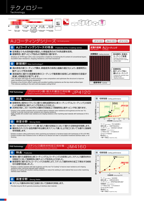
◆従来膜よりもAl含有量を増加した新組成系のAlTiN系皮膜を採用。
◆耐摩耗性・耐チッピング性および耐熱性に優れます。
◆詳細はカタログをダウンロードしご覧いただくか、お気軽にお問い合わせ下さい。
このカタログについて
| ドキュメント名 | アルファ 高送りラジアスミル ASR多刃タイプ |
|---|---|
| ドキュメント種別 | 製品カタログ |
| ファイルサイズ | 3.2Mb |
| 登録カテゴリ | |
| 取り扱い企業 | 株式会社MOLDINO (この企業の取り扱いカタログ一覧) |
この企業の関連カタログ


このカタログの内容
Page1
アルファ
高送りラジアスミルASR多刃タイプ
Radius Mill ASR Multi-flutes type
MOLDINO Tool Engineering, Ltd.
New Produc t News No.1207-17 2024-12
Page2
テクノロジー
Technology
JM4160 JP4105 荒 PVD Technology 高硬度材加工用材種
JS4045 JP4120 Grade for machining high-hardness materials JP4105
加工
GX2140 用途 Roughing
銅 炭素鋼 ステンレス鋼 プリハードン鋼 焼入れ鋼 焼入れ鋼 Applications 特長 Features 図 切削性能 Cutting performance
合金鋼 工具鋼 焼入れ鋼 45~55HRC 55~62HRC
30~45HRC 0.6
Copper Carbon steels Stainless steels Pre-hardened steels Hardened steels Hardened steels
Alloy steels Tool steels Hardened steels 45̃55HRC 55̃62HRC ● 耐摩耗性に優れた超微粒超硬母材と新コーティング「AJコーティング」の採用により
30̃45HRC
耐摩耗性を向上させました。 従来品
0.4 Conventional JP4105
● 50HRC~の高硬度材の切削加工で耐摩耗性に優れます。
AJコーティングシリーズ ・Employs an ultra-fine cemented carbide substrate and the new "AJ Coating" to improve wear resistance. 0.2
AJ Coating series JP4120 JM4160 JP4105 ・Excellent wear resistance when machining high hardness materials of 50HRC or higher.
0
AJコーティングシリーズの特長 0 5 10 15
Features of AJ Coating series 皮膜の組織 AJコーティング 得意分野 Strong fields 切削距離 Cutting length (m)
Layer structure AJ Coating ワーク Work material:SKD11(61HRC)
● 従来膜よりもAl含有量を増加した新組成系のAlTiN系皮膜を採用。 ● 焼入れ鋼(50~60HRC):SKD11,SKD61,SKH,SUS420系等 使用工具 Tool:ASRS2032-5
● 耐摩耗性・耐チッピング性および耐熱性に優れます。 皮膜構造 Coating structure 耐溶着性・低抵抗 インサート Insert:EPNW0603TN-8
・Hardened steels (50 to 60 HRC): SKD11, SKD61, SKH, SUS420, etc. 切削条件 Cutting conditions:
・Employs an AlTiN layer with a new composition created by increasing the Al content of conventional layers. コーティング表層 vc=80m/min fz=0.2mm/t
・Excellent wear resistance, chipping resistance, and heat resistance! Welding-resistant and
low-cutting-force coating ap×ae=0.5×21mm
surface layer 乾式加工 Dry ※単一刃加工 Single-flute cutting
新技術!! New technology!!
● 高Al含有の新コーティング膜は、新組成系の採用と組織の適正化により、耐摩耗性と PVD Technology 鋼一般加工用材種
耐摩耗性・ General purpose for steel JS4045
耐チッピング性を改善! 耐チッピング性に
● 耐溶着性に優れた低摩擦効果のコーティング最表層の採用により被削材の溶着が 優れたコーティング 特長 Features 皮膜の組織 JSコーティング
Coating with excellent wear
低減し切削抵抗が低下します。 Layer structure
resistance and JS Coating
・The new layer with high Al content employs a new composition and optimizes the structure to improve chipping resistance ● 耐熱性に優れたコーティング膜の採用により、高能率加工で発生するクレータ摩耗を低 皮膜構造 Coating structure
wear resistance and chipping resistance! 減しました。 耐熱性に優れた
・Employs a low-friction-effect coating with excellent welding resistance as the top-most surface layer. 超硬母材 Carbide
This reduces welding to the work and decreases cutting force! ● 耐熱性の高い超硬母材の採用により、摩耗の進行が低減し工具寿命に優れます。 コーティング
Heat resistant layer
● 特に乾式加工において長寿命が図れます。
・ JS4045 adopts heat resistant layer, reduces the crater wear by high-efficiency cutting. 耐摩耗性に優れた
PVD Technology プリハードン鋼・焼入れ鋼加工用材種 ・ JS4045 adopts heat resistant substrate, reduces the wear and improves tool life.
Grade for machining pre-hardened or hardened materials JP4120 コーティング
・ Especially improves tool life on dry cutting. Wear resistant layer
得意分野 Strong fields 耐熱性に優れた
特長 Features 図 切削性能 Cutting performance 超硬母材
● SS材、SC材、SCM材などの35HRC未満の連続~軽断続加工までの乾式加工。 Heat resistant substrate
● 耐摩耗性と靱性のバランスに優れた微粒超硬母材と新コーティング「AJコーティング」の採用 0.6
従来品B
Conventional B ・ continuous and light interrupted cutting of less than 35HRC dry cutting. 超硬母材 Carbide
により耐摩耗性と耐チッピング性を向上させました。 従来品A JP4120
● 汎用性が高く、30~50HRCの鋼材の切削加工で耐摩耗性と耐チッピング性に優れます。 0.4 Conventional A 従来品C 図 SCM440(32HRC)の切削試験結果 Wear graph after cutting SCM440(32HRC) 図 P20(32HRC)の切削試験結果 Wear graph after cutting P20(32HRC)
Conventional C
・Employs a fine carbide substrate with an excellent balance between wear resistance and toughness and the new "AJ
Coating" to provide improved wear resistance and chipping resistance. 0.4
0.2 切削条件 Cutting conditions 0.4 切削条件 Cutting conditions
・ Highly versatile with excellent wear resistance and chipping resistance when machining steel materials with hardnesses of 30 to 従来品 JS4045 従来品
被 削 材 SCM440(32HRC) Conventional JS4045
50 HRC. 被 削 材 P20(32HRC)
0.3 Conventional Work Material 0.3 Work Material
工 具 ASR5063-4 工 具 ASRS2016R-2
0 Tool Tool
0 10 20 30 40 50 60 0.2 インサート型番 EDNW15T4TN-15 0.2 インサート型番 EPNW0603TN-8
得意分野 切削距離 Cutting length (m) Insert Model Insert Model
Strong fields 切 削 速 度 vc = 180m/min 切 削 速 度 vc = 180m/min
0.1 Cutting Speed 0.1 Cutting Speed
ワーク Work material:P21(40HRC) 1刃当りの速度 fz = 1.5mm/t 1刃当りの速度 fz = 1.5mm/t
● 30~50HRCのプリハードン鋼・焼入れ鋼の切削加工において優れた切削性能を発揮します。 Speed per flute
使用工具 Tool:ASRT5063R-4 Speed per flute
0 切り込 み 0
● 難削系のダイカスト金型用鋼や析出硬化系ステンレス鋼、仕上げ加工においても優れた耐摩耗 インサート Insert:WDNW140520 0 50 100 150 ap×ae = 1.0 × 42mm
Cutting depth 0 100 200 300 切り込 み ap×ae = 0.5 × 13mm
切削距離 (m) Cutting length Dry(Air)加工 単一刃切削 切削距離 Cutting depth
切 削 油 剤 (m) Cutting length
性を発揮します。 切削条件 Cutting conditions: 切 削 油 剤 Dry(Air)加工 単一刃切削
Coolant Dry cutting Single-flute cutting Coolant Dry cutting Single-flute cutting
vc=90m/min fz=0.8mm/t
・Exhibits excellent cutting performance when machining pre-hardened or hardened steels with hardnesses of 30 to 50 HRC. ap×ae=1×44mm
・ Exhibits excellent wear resistance even on difficult-to-cut diecast tool steel or precipitation-hardened stainless steels, or for 乾式加工 Dry
※単一刃加工 CVD Technology 鋼一般加工用材種
finishing. Single-flute cutting General purpose for steel GX2140
特長 Features 皮膜の組織 GXコーティング
Layer structure
ステンレス鋼系材料加工用材種 GX Coating
PVD Technology ● 溶着性と耐チッピング性に優れる平滑化α-Al₂O₃膜の採用により、工具刃先の突発チッピ
GGrraaddee ffoorr mmaacchhiinniinngg ssttaaiinnlleessss--sstteeeell mmaatteerriiaallss JM416600 皮膜構造 表面平滑・厚膜α-Al2O3層
ングを抑制しました。 Coating structure Smooth surface and thick α-Al2O3 layer
耐溶着性・耐熱性改善
特長 ● 微細化柱状組織硬質皮膜の採用により、耐摩耗性に優れ高速乾式加工で加工能率の改善 Improved welding resistance and heat resistance
Features 図 切削性能 Cutting performance が図れます。 新アンカー効果Al2O3結合層
0.6
● 靱性に優れた超硬母材と新コーティング「AJコーティング」の採用により、ステンレス鋼系材料の 従来品 ・Smooth surfaced -Al2O3 coating with improved chipping / welding resistance brings less sudden-tool-edge-chipping. New anchor-effect Al2O3 bonding layer
Conventional Al2O3層の密着性改善
切削加工に対して耐摩耗性と耐チッピング性を向上させました。 ・Machining efficiency is improved for high-speed,high-feed-rate rough machining by using the hard-layer with fine columnar Improved adhesion to Al2O3 layer
0.4 structure.
● 耐溶着性に優れる「AJコーティング」の採用により、ステンレス鋼系材料の加工で発生する被削 微細化柱状組織硬質層
Hard layer with fine columnar structure
材の溶着を低減しました。 JM4160 得意分野 Strong fields 耐摩耗性・耐チッピング性改善
Improved wear resistance and chipping resistance
・Employs a carbide substrate with high toughness and the new "AJ Coating" to improve wear resistance and chipping 0.2
resistance when machining stainless-steel materials. ●SS材,SCM材,35HRC未満の工具鋼の切削加工において、優れた耐摩耗性能を発揮します。
・ 強靭性母材適用
Employs AJ Coating with excellent welding resistance to reduce the welding to work material that occurs when machining Tough substrate
stainless steel materials. 0 ・Exhibits superior wear resistance when cutting mild steel, carbon steels, alloy steels and tool steel use with hardnesses of 超硬母材 耐熱亀裂性・耐チッピング性改善
0 4 8 12 less than 35HRC. Carbide Improved high toughtness,thermal chipping resistance
切削距離 Cutting length (m)
図 S50C(220HB)の切削試験結果 Wear graph after cutting S50C(220HB) 図 P20(30HRC)の切削試験結果 Wear graph after cutting P20(30HRC)
得意分野 ワーク Work material:SUS304
Strong fields 使用工具 Tool:ASRS2032R-5 0.5 切削条件 Cutting conditions 0.5 切削条件 Cutting conditions
インサート Insert:EPMT0603EN-8LF
● ステンレス鋼系材料の加工全般において長寿命を実現します。 0.4
切削条件 Cutting conditions: 従来品 従来品 被 削 材 S50C(220HB) 0.4 被 削 材 P20(30HRC)
Conventional Conventional GX2140 Work Material 従来品 従来品 GX2140 Work Material
Conventional Conventional
・ vc=180m/min fz=0.5mm/t 0.3 使用ホルダー ASRT5063R-4 使用ホルダー ASRT5063R-4
Provides long tool life for general processing of stainless steel materials Holder used 0.3 Holder used
ap×ae=0.8×21mm インサート型番 WDNW140520 インサート型番 WDNW140520
0.2 Insert Model 0.2 Insert Model
湿式加工 Wet 切 削 速 度 vc = 180m/min 切 削 速 度 vc = 140m/min
※単一刃加工 Cutting Speed Cutting Speed
Single-flute cutting 0.1 1刃当りの速度 fz = 2.0mm/t 0.1 1刃当りの速度 fz = 1.4mm/t
Speed per flute Speed per flute
0 0
0 100 200 300 400 切り込 み ap×ae = 1 × 44mm 切 り込 み ap×ae = 1 × 43mm
Cutting depth 0 30 60 90 120 Cutting depth
切削距離 (m) Cutting length 切 削 油 剤 Dry加工 単一刃切削 切削距離 (m) Cutting length 切 削 油 剤 Dry加工 単一刃切削
Coolant Dry cutting Single-flute cutting Coolant Dry cutting Single-flute cutting
2
最大逃げ面摩耗幅 VBmax (mm) 最大逃げ面摩耗幅 VBmax (mm)
最大逃げ面摩耗幅 VBmax (mm) 最大逃げ面摩耗幅 VBmax (mm)
最大逃げ面摩耗幅 VBmax (mm) 最大逃げ面摩耗幅 VBmax (mm)
最大逃げ面摩耗幅 VBmax (mm)
Page3
テクノロジー
Technology
JM4160 JP4105 荒 PVD Technology 高硬度材加工用材種
JS4045 JP4120 Grade for machining high-hardness materials JP4105
加工
GX2140 用途 Roughing
銅 炭素鋼 ステンレス鋼 プリハードン鋼 焼入れ鋼 焼入れ鋼 Applications 特長 Features 図 切削性能 Cutting performance
合金鋼 工具鋼 焼入れ鋼 45~55HRC 55~62HRC
30~45HRC 0.6
Copper Carbon steels Stainless steels Pre-hardened steels Hardened steels Hardened steels
Alloy steels Tool steels Hardened steels 45̃55HRC 55̃62HRC ● 耐摩耗性に優れた超微粒超硬母材と新コーティング「AJコーティング」の採用により
30̃45HRC
耐摩耗性を向上させました。 従来品
0.4 Conventional JP4105
● 50HRC~の高硬度材の切削加工で耐摩耗性に優れます。
AJコーティングシリーズ ・Employs an ultra-fine cemented carbide substrate and the new "AJ Coating" to improve wear resistance. 0.2
AJ Coating series JP4120 JM4160 JP4105 ・Excellent wear resistance when machining high hardness materials of 50HRC or higher.
0
AJコーティングシリーズの特長 0 5 10 15
Features of AJ Coating series 皮膜の組織 AJコーティング 得意分野 Strong fields 切削距離 Cutting length (m)
Layer structure AJ Coating ワーク Work material:SKD11(61HRC)
● 従来膜よりもAl含有量を増加した新組成系のAlTiN系皮膜を採用。 ● 焼入れ鋼(50~60HRC):SKD11,SKD61,SKH,SUS420系等 使用工具 Tool:ASRS2032-5
● 耐摩耗性・耐チッピング性および耐熱性に優れます。 皮膜構造 Coating structure 耐溶着性・低抵抗 インサート Insert:EPNW0603TN-8
・Hardened steels (50 to 60 HRC): SKD11, SKD61, SKH, SUS420, etc. 切削条件 Cutting conditions:
・Employs an AlTiN layer with a new composition created by increasing the Al content of conventional layers. コーティング表層 vc=80m/min fz=0.2mm/t
・Excellent wear resistance, chipping resistance, and heat resistance! Welding-resistant and
low-cutting-force coating ap×ae=0.5×21mm
surface layer 乾式加工 Dry ※単一刃加工 Single-flute cutting
新技術!! New technology!!
● 高Al含有の新コーティング膜は、新組成系の採用と組織の適正化により、耐摩耗性と PVD Technology 鋼一般加工用材種
耐摩耗性・ General purpose for steel JS4045
耐チッピング性を改善! 耐チッピング性に
● 耐溶着性に優れた低摩擦効果のコーティング最表層の採用により被削材の溶着が 優れたコーティング 特長 Features 皮膜の組織 JSコーティング
Coating with excellent wear
低減し切削抵抗が低下します。 Layer structure
resistance and JS Coating
・The new layer with high Al content employs a new composition and optimizes the structure to improve chipping resistance ● 耐熱性に優れたコーティング膜の採用により、高能率加工で発生するクレータ摩耗を低 皮膜構造 Coating structure
wear resistance and chipping resistance! 減しました。 耐熱性に優れた
・Employs a low-friction-effect coating with excellent welding resistance as the top-most surface layer. 超硬母材 Carbide
This reduces welding to the work and decreases cutting force! ● 耐熱性の高い超硬母材の採用により、摩耗の進行が低減し工具寿命に優れます。 コーティング
Heat resistant layer
● 特に乾式加工において長寿命が図れます。
・ JS4045 adopts heat resistant layer, reduces the crater wear by high-efficiency cutting. 耐摩耗性に優れた
PVD Technology プリハードン鋼・焼入れ鋼加工用材種 ・ JS4045 adopts heat resistant substrate, reduces the wear and improves tool life.
Grade for machining pre-hardened or hardened materials JP4120 コーティング
・ Especially improves tool life on dry cutting. Wear resistant layer
得意分野 Strong fields 耐熱性に優れた
特長 Features 図 切削性能 Cutting performance 超硬母材
● SS材、SC材、SCM材などの35HRC未満の連続~軽断続加工までの乾式加工。 Heat resistant substrate
● 耐摩耗性と靱性のバランスに優れた微粒超硬母材と新コーティング「AJコーティング」の採用 0.6
従来品B
Conventional B ・ continuous and light interrupted cutting of less than 35HRC dry cutting. 超硬母材 Carbide
により耐摩耗性と耐チッピング性を向上させました。 従来品A JP4120
● 汎用性が高く、30~50HRCの鋼材の切削加工で耐摩耗性と耐チッピング性に優れます。 0.4 Conventional A 従来品C 図 SCM440(32HRC)の切削試験結果 Wear graph after cutting SCM440(32HRC) 図 P20(32HRC)の切削試験結果 Wear graph after cutting P20(32HRC)
Conventional C
・Employs a fine carbide substrate with an excellent balance between wear resistance and toughness and the new "AJ
Coating" to provide improved wear resistance and chipping resistance. 0.4
0.2 切削条件 Cutting conditions 0.4 切削条件 Cutting conditions
・ Highly versatile with excellent wear resistance and chipping resistance when machining steel materials with hardnesses of 30 to 従来品 JS4045 従来品
被 削 材 SCM440(32HRC) Conventional JS4045
50 HRC. 被 削 材 P20(32HRC)
0.3 Conventional Work Material 0.3 Work Material
工 具 ASR5063-4 工 具 ASRS2016R-2
0 Tool Tool
0 10 20 30 40 50 60 0.2 インサート型番 EDNW15T4TN-15 0.2 インサート型番 EPNW0603TN-8
得意分野 切削距離 Cutting length (m) Insert Model Insert Model
Strong fields 切 削 速 度 vc = 180m/min 切 削 速 度 vc = 180m/min
0.1 Cutting Speed 0.1 Cutting Speed
ワーク Work material:P21(40HRC) 1刃当りの速度 fz = 1.5mm/t 1刃当りの速度 fz = 1.5mm/t
● 30~50HRCのプリハードン鋼・焼入れ鋼の切削加工において優れた切削性能を発揮します。 Speed per flute
使用工具 Tool:ASRT5063R-4 Speed per flute
0 切り込 み 0
● 難削系のダイカスト金型用鋼や析出硬化系ステンレス鋼、仕上げ加工においても優れた耐摩耗 インサート Insert:WDNW140520 0 50 100 150 ap×ae = 1.0 × 42mm
Cutting depth 0 100 200 300 切り込 み ap×ae = 0.5 × 13mm
切削距離 (m) Cutting length Dry(Air)加工 単一刃切削 切削距離 Cutting depth
切 削 油 剤 (m) Cutting length
性を発揮します。 切削条件 Cutting conditions: 切 削 油 剤 Dry(Air)加工 単一刃切削
Coolant Dry cutting Single-flute cutting Coolant Dry cutting Single-flute cutting
vc=90m/min fz=0.8mm/t
・Exhibits excellent cutting performance when machining pre-hardened or hardened steels with hardnesses of 30 to 50 HRC. ap×ae=1×44mm
・ Exhibits excellent wear resistance even on difficult-to-cut diecast tool steel or precipitation-hardened stainless steels, or for 乾式加工 Dry
※単一刃加工 CVD Technology 鋼一般加工用材種
finishing. Single-flute cutting General purpose for steel GX2140
特長 Features 皮膜の組織 GXコーティング
Layer structure
ステンレス鋼系材料加工用材種 GX Coating
PVD Technology ● 溶着性と耐チッピング性に優れる平滑化α-Al₂O₃膜の採用により、工具刃先の突発チッピ
GGrraaddee ffoorr mmaacchhiinniinngg ssttaaiinnlleessss--sstteeeell mmaatteerriiaallss JM416600 皮膜構造 表面平滑・厚膜α-Al2O3層
ングを抑制しました。 Coating structure Smooth surface and thick α-Al2O3 layer
耐溶着性・耐熱性改善
特長 ● 微細化柱状組織硬質皮膜の採用により、耐摩耗性に優れ高速乾式加工で加工能率の改善 Improved welding resistance and heat resistance
Features 図 切削性能 Cutting performance が図れます。 新アンカー効果Al2O3結合層
0.6
● 靱性に優れた超硬母材と新コーティング「AJコーティング」の採用により、ステンレス鋼系材料の 従来品 ・Smooth surfaced -Al2O3 coating with improved chipping / welding resistance brings less sudden-tool-edge-chipping. New anchor-effect Al2O3 bonding layer
Conventional Al2O3層の密着性改善
切削加工に対して耐摩耗性と耐チッピング性を向上させました。 ・Machining efficiency is improved for high-speed,high-feed-rate rough machining by using the hard-layer with fine columnar Improved adhesion to Al2O3 layer
0.4 structure.
● 耐溶着性に優れる「AJコーティング」の採用により、ステンレス鋼系材料の加工で発生する被削 微細化柱状組織硬質層
Hard layer with fine columnar structure
材の溶着を低減しました。 JM4160 得意分野 Strong fields 耐摩耗性・耐チッピング性改善
Improved wear resistance and chipping resistance
・Employs a carbide substrate with high toughness and the new "AJ Coating" to improve wear resistance and chipping 0.2
resistance when machining stainless-steel materials. ●SS材,SCM材,35HRC未満の工具鋼の切削加工において、優れた耐摩耗性能を発揮します。
・ 強靭性母材適用
Employs AJ Coating with excellent welding resistance to reduce the welding to work material that occurs when machining Tough substrate
stainless steel materials. 0 ・Exhibits superior wear resistance when cutting mild steel, carbon steels, alloy steels and tool steel use with hardnesses of 超硬母材 耐熱亀裂性・耐チッピング性改善
0 4 8 12 less than 35HRC. Carbide Improved high toughtness,thermal chipping resistance
切削距離 Cutting length (m)
図 S50C(220HB)の切削試験結果 Wear graph after cutting S50C(220HB) 図 P20(30HRC)の切削試験結果 Wear graph after cutting P20(30HRC)
得意分野 ワーク Work material:SUS304
Strong fields 使用工具 Tool:ASRS2032R-5 0.5 切削条件 Cutting conditions 0.5 切削条件 Cutting conditions
インサート Insert:EPMT0603EN-8LF
● ステンレス鋼系材料の加工全般において長寿命を実現します。 0.4
切削条件 Cutting conditions: 従来品 従来品 被 削 材 S50C(220HB) 0.4 被 削 材 P20(30HRC)
Conventional Conventional GX2140 Work Material 従来品 従来品 GX2140 Work Material
Conventional Conventional
・ vc=180m/min fz=0.5mm/t 0.3 使用ホルダー ASRT5063R-4 使用ホルダー ASRT5063R-4
Provides long tool life for general processing of stainless steel materials Holder used 0.3 Holder used
ap×ae=0.8×21mm インサート型番 WDNW140520 インサート型番 WDNW140520
0.2 Insert Model 0.2 Insert Model
湿式加工 Wet 切 削 速 度 vc = 180m/min 切 削 速 度 vc = 140m/min
※単一刃加工 Cutting Speed Cutting Speed
Single-flute cutting 0.1 1刃当りの速度 fz = 2.0mm/t 0.1 1刃当りの速度 fz = 1.4mm/t
Speed per flute Speed per flute
0 0
0 100 200 300 400 切り込 み ap×ae = 1 × 44mm 切 り込 み ap×ae = 1 × 43mm
Cutting depth 0 30 60 90 120 Cutting depth
切削距離 (m) Cutting length 切 削 油 剤 Dry加工 単一刃切削 切削距離 (m) Cutting length 切 削 油 剤 Dry加工 単一刃切削
Coolant Dry cutting Single-flute cutting Coolant Dry cutting Single-flute cutting
3
最大逃げ面摩耗幅 VBmax (mm) 最大逃げ面摩耗幅 VBmax (mm)
最大逃げ面摩耗幅 VBmax (mm) 最大逃げ面摩耗幅 VBmax (mm)
最大逃げ面摩耗幅 VBmax (mm) 最大逃げ面摩耗幅 VBmax (mm)
最大逃げ面摩耗幅 VBmax (mm)
Page4
ラインナップ
Line Up
は数字、 は英文字が入ります。
ストレートシャンクタイプ Numeric figure in a circle and
Straight Shank Type ASR 20 ( )R- Alphabetical character comes in a square ボアタイプ Bore Type ASR (R M)- は数字が入ります。
Numeric figure in a circle .
DHUB DHUB
DCONMS DCONMS
b KWW b KWW
LH LS LH LS
LF LF
Fig.1(一般形) Fig.2(アンダーカット形)
エアー穴付き
Standard type Undercut type With air hole
寸法 Size (mm)
商品コード 在庫 刃数 形状 適用インサート 希望小売価格(円) DCCB DCCB
Suggested
Item code Stock No.of
flutes DCX LF DCONMS LH LS θκ Shape Inserts retail price (¥)
レ ASRS2016R-2 ● 2 16 100 16 30 70 ̶ 40,650 DCX DCX
ギ エアー穴付き
ュ ASRS2020R-3 ● 3 20 130 20 50 80 ̶ 52,410 Fig.3 Fig.4 With air hole
ラ ASRS2025R-4 ● 4 25 140 25 60 80 ̶ Fig.1 63,230
ー ASRS2030R-4 ● 4 30 150 32 70 80 0.9° 66,730 商品コード 在庫 刃数 寸法 Size (mm) 形状 適用インサート 希望小売価格(円)
ASRS2032R-5 ● 5 32 150 32 70 80 ̶ 75,240 Item code Sto DCX DHUB LF CBDP KWW b DCONMS DCCB Suggested
ck No.of
flutes Shape Inserts retail price (¥)
シ ASRS2040R-6 ● 6 40 150 32 45 105 ̶ Fig.2 86,600 ボ 内径 ASR3050R-5 ● 5 50 47 50 19 8.4 5 22.225 17 EDNW12T3TN-10 95,110
ャ ASRL2016R-2 ● 2 16 150 16 50 100 ̶ Fig.1 46,340
ン ア インチ
サイズ ASR3063R-6 ● 6 63 60 50 19 8.4 5 22.225 17 Fig.3 EDMT12T3TN-10 102,210
ク ASRL2016S15R-2 ● 2 16 150 15 25 125 ̶ 46,340 タ Internal ASR2052R-7 ● 7 52 47 50 19 8.4 5 22.225 17 EPNW0603TN-8 106,460
タ ASRL2018R-2 ● 2 18 150 16 25 125 ̶ Fig.2 46,340 イ diameter EPMT0603TN-8
ASRL2020R-3 ● 3 20 160 20 80 80 ̶ Fig.1 EPNW0603TN-8
イ 59,620 プ inch size ASR2066R-8 ● 8 66 60 50 19 8.4 5 22.225 17 Fig.4
EPMT0603EN-8LF 113,560
プ EPMT0603TN-8
ASRL2020S18R-3 ● 3 20 160 18 30 130 ̶ 59,620 内径 ASR3050RM-5 ● 5 50 47 50 20 10.4 6.3 22 17 EDNW12T3TN-10 95,110
EPMT0603EN-8LF ミリ
ロ ASRL2022R-3 ● 3 22 160 20 30 130 ̶ Fig.2 59,620 サイズ ASR3063RM-6 ● 6 63 60 50 20 10.4 6.3 22 17 Fig.3 EDMT12T3TN-10 102,210
ン Internal ASR2052RM-7 ● 7 52 47 50 20 10.4 6.3 22 17 EPNW0603TN-8 106,460
グ ASRL2025R-4 ● 4 25 180 25 100 80 ̶ Fig.1 66,730 diameter EPMT0603TN-8
ASRL2025S23R-4 ● 4 25 180 23 35 145 ̶ 66,730 mm size ASR2066RM-8 ● 8 66 60 50 20 10.4 6.3 22 17 Fig.4
EPMT0603EN-8LF 113,560
ASRL2028R-4 ● 4 28 180 25 35 145 ̶ Fig.2 66,730 【注意】アーバ用ねじは付属しません。【Note】Arbor screw is not included.
ASRL2030R-4 ● 4 30 200 32 120 80 0.6° Fig.1 69,440
ASRL2030S28R-4 ● 4 30 200 28 40 160 ̶ Fig.2 69,440
ASRL2032R-5 ● 5 32 200 32 120 80 ̶ Fig.1 77,950 インサート Inserts
ASRL2032S30R-5 ● 5 32 200 30 40 160 ̶ 77,950
ASRL2040R-6 ● 6 40 220 32 45 175 ̶ Fig.2 90,850 標準形状 ブレーカ付 ねじれ形状(低抵抗)
Standard shape With breaker Spiral shape (low cutting force)
モジュラータイプ Modular Type ASRM20 R- は数字が入ります。
Numeric figure in a circle . R R R
LF
THSZMS DRVS(二面幅)
INSL S INSL S INSL S
Fig.5 Fig.6 Fig.7
P 鋼 Carbon steels
M SUS等 SUS, etc. :一般切削・第一推奨 General cutting, First recommended
K FC・FCD Cast irons :一般切削・第二推奨 General cutting, Second recommended
H 高硬度材 Hardened steels
L1 エアー穴付き
L2 AJコーティング GXコーティング JSコーティング 寸法
With air hole
商品 AJ Coating GX Coating JS Coating
コード 精度 Size(mm) 形状 希望小売価格(円)
商品コード 在庫 刃数 寸法 Size (mm) 適用 Tolerance
インサート 希望小売価格(円) Item code Shape Suggested retail price(¥)
Suggested class
Item code Stock No.of JP4105 JP4120 JM4160 GX2140 JS4045 JS4060 R INSL S W1
flutes DCX LF DCONMS THSZMS DHUB L1 L2 DRVS Inserts retail price (¥)
ASRM2016R-2 ● 2 16 25 8.5 M8 12.8 5.5 17 10 40,650 EPNW0603TN-8
※ N級 ● ● ● ● ● ● 8 10 3.18 6.35 1,210
1 ASRM2018R-2 ● 2 18 25 8.5 M8 14.5 5.5 17 10 40,650 Fig.5
EDNW12T3TN-10 N ● ● ● ● ● ● 10 12 3.97 10 1,650
ASRM2020R-3 ● 3 20 30 10.5 M10 17.8 5.5 19 15 52,410
※ EPMT0603TN-8 ● ● ● ● ● ● 8 10 3.18 6.35 1,210
1 ASRM2022R-3 ● 3 22 30 10.5 M10 17.8 5.5 19 15 EPNW0603TN-8 52,410
ASRM2025R-4 ● 4 25 35 12.5 M12 20.8 5.5 22 17 EPMT0603TN-8 63,230 EDMT12T3TN-10 M級 Fig.6
● ● ● ● ● ●
M 10 12 3.97 10 1,650
※1 ASRM2028R-4 ● 4 28 35 12.5 M12 23 5.5 22 17 EPMT0603EN-8LF 63,230 EPMT0603EN-8LF ● 8 10 3.18 6.35 Fig.7 1,210
ASRM2030R-4 ● 4 30 40 17 M16 28.8 6 23 22 66,730 【注意】GXコーティング、JSコーティングは通電式タッチセンサーに反応しませんのでご注意ください。
ASRM2032R-5 ● 5 32 40 17 M16 28.8 6 23 22 75,240 【Note】Please note that the GX Coating and JS Coating do not cause a reaction in conductive touch sensors.
※1 ASRM2040R-6 ● 6 40 40 17 M16 28.8 6 23 22 86,600
【注意】※1と※2(P7)をセットで使用すると干渉がありません。
モジュラーミル及び専用シャンク、専用アーバの「工具端面」「モジュラーねじ部」にグリースなどの潤滑剤は塗布しないでください。
【Note】When ※1 and※2 (p7) are used together as a set, there is no interference. 材種マップ(35HRC未満の鋼材) 被削材別推奨材種マップ Grade map for work materials
Do not apply lubricants such as grease, etc. to the "contact faces" and "modular screws" of the "modular mill", "dedicated shanks" and "dedicated arbor". Grade map for less than 35HRC 被削材硬度 Work Hardness 被削材硬度 Work Hardness 被削材硬度 Work Hardness
低い Low High 高い 低い Low High 高い 低い Low High 高い
部品番号 ◀耐チッピング性 Chipping resistance 耐摩耗性 Wear resistance▶
Parts は数字が入ります。 Numeric figure in a circle . 不
部品名 クランプねじ クランプ駒セット ドライバー GX2140 安
定 JS4060 JS4045
/レンチ ねじ焼き付き防止剤 加 JM4160
工
Parts Clamp screw Clamp piece set Screw driver / Wrench Screw anti-seizure agent JS4045 GX2140
形状 JS4060 JS4045
Shape 締付 希望小売 希望小売 希望小売 希望小売
適用カッタ トルク 価格(円) 価格(円) 形状 価格(円) 価格(円)
Fastening JP4120
Suggested Suggested Suggested Suggested
torque retail retail A B Shape
Cutter body retail retail ◀湿式加工 Wet cutting 乾式加工 Dry cutting▶
(N・m) price (¥) price (¥) price (¥) price (¥) JP4105 JP4120 JP4120
ASR S/L/M20 (S )R- GX2140 安
定 GX2140
ASR 20 R(M)- 250-141 1.1 960 ー - 104-T8 A 1,980
P-37 1,120 加
ASR 30 R(M)- 412-141 2.9 600 CM3.5-141 2,240 105-T15 JS4045 工
B 2,340 一般構造用鋼 炭素鋼・合金鋼 炭素鋼・合金鋼 焼入れ鋼 焼入れ鋼 ステンレス鋼系材料 鋳鉄
【注意】クランプねじは消耗品です。使用環境により交換寿命は変化しますので早めの交換をお願い致します。クランプねじは予備が2本付属します。 JS4060 (200HB以下)(30HRC以下)(30~45HRC)(45~50HRC)(50~60HRC) SUS FC,FCD
Mild steels Carbon steels, Alloy steels Carbon steels Hardened steels Hardened steels Stainless steel materials Cast irons
(200HB or less) (30HRC or less) Alloy steels
【Note】The clamp screw is a consumable part. Since replacement life depends on the use environment, it is recommended that it be replaced at an early stage.
Includes two spare clamp screws.
●印:標準在庫品です。●:Stocked Items.
4
Shank type
Long Regular
DCX
DCX
DCONMS
DCONMS
DCX
DHUB
DCONMS
Bore type
Unstable Stable W1
machining machining
CBDP
LF
W1
CBDP
LF
W1
Page5
ラインナップ
Line Up
は数字、 は英文字が入ります。
ストレートシャンクタイプ Numeric figure in a circle and
Straight Shank Type ASR 20 ( )R- Alphabetical character comes in a square ボアタイプ Bore Type ASR (R M)- は数字が入ります。
Numeric figure in a circle .
DHUB DHUB
DCONMS DCONMS
b KWW b KWW
LH LS LH LS
LF LF
Fig.1(一般形) Fig.2(アンダーカット形)
エアー穴付き
Standard type Undercut type With air hole
寸法 Size (mm)
商品コード 在庫 刃数 形状 適用インサート 希望小売価格(円) DCCB DCCB
Suggested
Item code Stock No.of
flutes DCX LF DCONMS LH LS θκ Shape Inserts retail price (¥)
レ ASRS2016R-2 ● 2 16 100 16 30 70 ̶ 40,650 DCX DCX
ギ エアー穴付き
ュ ASRS2020R-3 ● 3 20 130 20 50 80 ̶ 52,410 Fig.3 Fig.4 With air hole
ラ ASRS2025R-4 ● 4 25 140 25 60 80 ̶ Fig.1 63,230
ー ASRS2030R-4 ● 4 30 150 32 70 80 0.9° 66,730 商品コード 在庫 刃数 寸法 Size (mm) 形状 適用インサート 希望小売価格(円)
ASRS2032R-5 ● 5 32 150 32 70 80 ̶ 75,240 Item code Sto DCX DHUB LF CBDP KWW b DCONMS DCCB Suggested
ck No.of
flutes Shape Inserts retail price (¥)
シ ASRS2040R-6 ● 6 40 150 32 45 105 ̶ Fig.2 86,600 ボ 内径 ASR3050R-5 ● 5 50 47 50 19 8.4 5 22.225 17 EDNW12T3TN-10 95,110
ャ ASRL2016R-2 ● 2 16 150 16 50 100 ̶ Fig.1 46,340
ン ア インチ
サイズ ASR3063R-6 ● 6 63 60 50 19 8.4 5 22.225 17 Fig.3 EDMT12T3TN-10 102,210
ク ASRL2016S15R-2 ● 2 16 150 15 25 125 ̶ 46,340 タ Internal ASR2052R-7 ● 7 52 47 50 19 8.4 5 22.225 17 EPNW0603TN-8 106,460
タ ASRL2018R-2 ● 2 18 150 16 25 125 ̶ Fig.2 46,340 イ diameter EPMT0603TN-8
ASRL2020R-3 ● 3 20 160 20 80 80 ̶ Fig.1 EPNW0603TN-8
イ 59,620 プ inch size ASR2066R-8 ● 8 66 60 50 19 8.4 5 22.225 17 Fig.4
EPMT0603EN-8LF 113,560
プ EPMT0603TN-8
ASRL2020S18R-3 ● 3 20 160 18 30 130 ̶ 59,620 内径 ASR3050RM-5 ● 5 50 47 50 20 10.4 6.3 22 17 EDNW12T3TN-10 95,110
EPMT0603EN-8LF ミリ
ロ ASRL2022R-3 ● 3 22 160 20 30 130 ̶ Fig.2 59,620 サイズ ASR3063RM-6 ● 6 63 60 50 20 10.4 6.3 22 17 Fig.3 EDMT12T3TN-10 102,210
ン Internal ASR2052RM-7 ● 7 52 47 50 20 10.4 6.3 22 17 EPNW0603TN-8 106,460
グ ASRL2025R-4 ● 4 25 180 25 100 80 ̶ Fig.1 66,730 diameter EPMT0603TN-8
ASRL2025S23R-4 ● 4 25 180 23 35 145 ̶ 66,730 mm size ASR2066RM-8 ● 8 66 60 50 20 10.4 6.3 22 17 Fig.4
EPMT0603EN-8LF 113,560
ASRL2028R-4 ● 4 28 180 25 35 145 ̶ Fig.2 66,730 【注意】アーバ用ねじは付属しません。【Note】Arbor screw is not included.
ASRL2030R-4 ● 4 30 200 32 120 80 0.6° Fig.1 69,440
ASRL2030S28R-4 ● 4 30 200 28 40 160 ̶ Fig.2 69,440
ASRL2032R-5 ● 5 32 200 32 120 80 ̶ Fig.1 77,950 インサート Inserts
ASRL2032S30R-5 ● 5 32 200 30 40 160 ̶ 77,950
ASRL2040R-6 ● 6 40 220 32 45 175 ̶ Fig.2 90,850 標準形状 ブレーカ付 ねじれ形状(低抵抗)
Standard shape With breaker Spiral shape (low cutting force)
モジュラータイプ Modular Type ASRM20 R- は数字が入ります。
Numeric figure in a circle . R R R
LF
THSZMS DRVS(二面幅)
INSL S INSL S INSL S
Fig.5 Fig.6 Fig.7
P 鋼 Carbon steels
M SUS等 SUS, etc. :一般切削・第一推奨 General cutting, First recommended
K FC・FCD Cast irons :一般切削・第二推奨 General cutting, Second recommended
H 高硬度材 Hardened steels
L1 エアー穴付き
L2 AJコーティング GXコーティング JSコーティング 寸法
With air hole
商品 AJ Coating GX Coating JS Coating
コード 精度 Size(mm) 形状 希望小売価格(円)
商品コード 在庫 刃数 寸法 Size (mm) 適用 Tolerance
インサート 希望小売価格(円) Item code Shape Suggested retail price(¥)
Suggested class
Item code Stock No.of JP4105 JP4120 JM4160 GX2140 JS4045 JS4060 R INSL S W1
flutes DCX LF DCONMS THSZMS DHUB L1 L2 DRVS Inserts retail price (¥)
ASRM2016R-2 ● 2 16 25 8.5 M8 12.8 5.5 17 10 40,650 EPNW0603TN-8
※ N級 ● ● ● ● ● ● 8 10 3.18 6.35 1,210
1 ASRM2018R-2 ● 2 18 25 8.5 M8 14.5 5.5 17 10 40,650 Fig.5
EDNW12T3TN-10 N ● ● ● ● ● ● 10 12 3.97 10 1,650
ASRM2020R-3 ● 3 20 30 10.5 M10 17.8 5.5 19 15 52,410
※ EPMT0603TN-8 ● ● ● ● ● ● 8 10 3.18 6.35 1,210
1 ASRM2022R-3 ● 3 22 30 10.5 M10 17.8 5.5 19 15 EPNW0603TN-8 52,410
ASRM2025R-4 ● 4 25 35 12.5 M12 20.8 5.5 22 17 EPMT0603TN-8 63,230 EDMT12T3TN-10 M級 Fig.6
● ● ● ● ● ●
M 10 12 3.97 10 1,650
※1 ASRM2028R-4 ● 4 28 35 12.5 M12 23 5.5 22 17 EPMT0603EN-8LF 63,230 EPMT0603EN-8LF ● 8 10 3.18 6.35 Fig.7 1,210
ASRM2030R-4 ● 4 30 40 17 M16 28.8 6 23 22 66,730 【注意】GXコーティング、JSコーティングは通電式タッチセンサーに反応しませんのでご注意ください。
ASRM2032R-5 ● 5 32 40 17 M16 28.8 6 23 22 75,240 【Note】Please note that the GX Coating and JS Coating do not cause a reaction in conductive touch sensors.
※1 ASRM2040R-6 ● 6 40 40 17 M16 28.8 6 23 22 86,600
【注意】※1と※2(P7)をセットで使用すると干渉がありません。
モジュラーミル及び専用シャンク、専用アーバの「工具端面」「モジュラーねじ部」にグリースなどの潤滑剤は塗布しないでください。
【Note】When ※1 and※2 (p7) are used together as a set, there is no interference. 材種マップ(35HRC未満の鋼材) 被削材別推奨材種マップ Grade map for work materials
Do not apply lubricants such as grease, etc. to the "contact faces" and "modular screws" of the "modular mill", "dedicated shanks" and "dedicated arbor". Grade map for less than 35HRC 被削材硬度 Work Hardness 被削材硬度 Work Hardness 被削材硬度 Work Hardness
低い Low High 高い 低い Low High 高い 低い Low High 高い
部品番号 ◀耐チッピング性 Chipping resistance 耐摩耗性 Wear resistance▶
Parts は数字が入ります。 Numeric figure in a circle . 不
部品名 クランプねじ クランプ駒セット ドライバー GX2140 安
定 JS4060 JS4045
/レンチ ねじ焼き付き防止剤 加 JM4160
工
Parts Clamp screw Clamp piece set Screw driver / Wrench Screw anti-seizure agent JS4045 GX2140
形状 JS4060 JS4045
Shape 締付 希望小売 希望小売 希望小売 希望小売
適用カッタ トルク 価格(円) 価格(円) 形状 価格(円) 価格(円)
Fastening JP4120
Suggested Suggested Suggested Suggested
torque retail retail A B Shape
Cutter body retail retail ◀湿式加工 Wet cutting 乾式加工 Dry cutting▶
(N・m) price (¥) price (¥) price (¥) price (¥) JP4105 JP4120 JP4120
ASR S/L/M20 (S )R- GX2140 安
定 GX2140
ASR 20 R(M)- 250-141 1.1 960 ー - 104-T8 A 1,980
P-37 1,120 加
ASR 30 R(M)- 412-141 2.9 600 CM3.5-141 2,240 105-T15 JS4045 工
B 2,340 一般構造用鋼 炭素鋼・合金鋼 炭素鋼・合金鋼 焼入れ鋼 焼入れ鋼 ステンレス鋼系材料 鋳鉄
【注意】クランプねじは消耗品です。使用環境により交換寿命は変化しますので早めの交換をお願い致します。クランプねじは予備が2本付属します。 JS4060 (200HB以下)(30HRC以下)(30~45HRC)(45~50HRC)(50~60HRC) SUS FC,FCD
Mild steels Carbon steels, Alloy steels Carbon steels Hardened steels Hardened steels Stainless steel materials Cast irons
(200HB or less) (30HRC or less) Alloy steels
【Note】The clamp screw is a consumable part. Since replacement life depends on the use environment, it is recommended that it be replaced at an early stage.
Includes two spare clamp screws.
●印:標準在庫品です。●:Stocked Items. 無印:受注生産品です。No Mark:Manufactured upon request only.
5
Shank type
Long Regular
DCX
DCX
DCONMS
DCONMS
DCX
DHUB
DCONMS
Bore type
Unstable Stable W1
machining machining
CBDP
LF
W1
CBDP
LF
W1
Page6
ASR多刃タイプ 位置付け ラインナップ
ASR Mul t i - f lu tes type posi t ion Line Up
従来品に対して、更なる高能率化を計るため、小径側 小さなインサートにもかかわらず大幅に耐チッピン モジュラーミル専用シャンク Special Shanks for Modular Mills
のφ16~φ66まで多刃化を計りました。 グ性を向上させ、fz≧1.5mm/tで使用が可能とし
■ 超硬シャンク Carbide Shank LF
In order to provide even higher performance compared to conventional tools, たことから、最新の工作機械の最大切削送り(Vf≧ LF
LB1 LS Cタイプ LB1 LS Eタイプ
holders from the small-diameter side of φ16mm to φ66mm were made C type E type
multi-flutes. 20m/min)で、ご使用頂けます。この効果として、
加工能率は大幅にアップが可能となりました。 THSZWS THSZWS
工具径DCX( mm) Tool dia.
Even for small inserts, chipping resistance has been greatly improved, enabling use at fz≧
10 20 30 40 50 60 80 100
0 1.5mm/t, so that use at the maximum machining feed rate of the latest machining equipment (Vf 商品コード 在庫 寸 法 Size(mm) タイプ 適用カッタ エアー穴有無 希望小売価格(円)
n.) is recommended. As a result, processing performance can be drastically improved. Item code Stock Type Cutter body With/ Suggested
DCONWS THSZWS LF LB1 LS BD1 DCONMS D1 without air hole retail price (¥)
φ16 φ66 ≧20m/mi
ASC16-8.5-95-30Z ● 95 30 65 52,910
~ ASC16-8.5-120-55Z ● 120 55 65
100 φ16※ 57,820
3
ASC16-8.5-140-75Z ● 8.5 M8 140 75 65 14.5 16 15.5 C φ18 ○ 61,560
ASR多刃タイプ ASC16-8.5-160-95Z ● 160 95 65 64,790
ASR多刃タイプ 300 ASR Multi-flutes type
ASR Multi-flutes type ※2 ASC16-8.5-160-30Z ● 160 30 130 64,790
200 ASC20-10.5-120-50Z ● 120 50 70 62,460
(従来) ap=0.3~0.5mm ASC20-10.5-170-90Z ● 10.5 M10 170 90 80 φ20※3 69,950
Conventional 18.5 20 19.5 C φ22 ○
200 ASR ASC20-10.5-220-120Z ● 220 120 100 76,920
一般 ASC20-10.5-270-150Z ● 270 150 120 97,560
300 ップ
工具 能率ア ※2 ASC20-10.5-220-50Z ● 10.5 M10 220 170 φ20※3 76,920
General Efficiency up ※2 SC20-10.5-270-50Z ● 270 50 220 18.5 20 19.5 C φ22 ○
A 97,560
100 tool
ASRF(4コーナ) ASC25-12.5-145-65 ● 145 65 80 71,490
4-corners
a 5-12.5-215-115 ● φ25※3 83,750
p≦1.5mm ASC2
00 12.5 M12 215 115 100
4 23 25 ̶ E φ28 ○
ASC25-12.5-265-145 ● 265 145 120 97,560
0 0 125,810
0 5 20 30 40 50 60 ASC25-12.5-315-195 ● 315 195 12
工作機械の切削送り速度 v ※2 -65 ● φ25※3 97,560
f ASC25-12.5-265
Machining equipment table feed rate( m/min) 12.5 M12 265 200
※2 5-12.5-315-65 ● 315 65 250 23 25 ̶ E φ28 ○
ASC2 125,810
ASC32-17-160-80 ● 160 80 80 108,400
ASC32-17-210-110 ● 210 110 100 φ30※3 109,690
ASC32-17-260-140 ● 17 M16 260 140 120 28 32 ̶ E φ32※3 ○ 130,330
当社高送 ASC32-17-310-190 ● 310 190 120 〈φ40〉 176,790
り工具のラインナップ High-feed tools lineup ASC32-17-360-240 ● 360 240 120 223,230
特長 ※2 ASC32-17-260-80 ● 260 180 φ30※3 130,330
Features ホルダ Holders インサート Inserts
※2 ASC32-17-310-80 ● 17 M16 310 80 230 28 32 ̶ E φ32※3 ○
能率 プログラ 176,790
型式 経済性 高精度 高硬度 ※2 ASC32-17-360-80 ● 360 280 〈φ40〉
対応 (刃数) 工具径 コーナ数 形状 内接円記号 ミング R APMX 223,230
Type (コーナ数) (削り残し小) Tool dia. Inscribed Programming R (mm)
Economical High accuracy Supports for high- Efficiency No. of corners Shape 【注意】①※2と※1(P4)をセットで使用すると干渉がありません。 【Note】①When※2 and※1 (P4) are used together as a set, there is no interference.
(mm) circle code (mm)
(No. of corners) (Less uncut remnants) hardened steel (No. of Flutes) ②市販のミ-リングチャック、焼ばめホルダーにて使用できます。 ②Commercial milling chucks or shrink-fit holders can be used.
◎ ③〈φ40〉寸法は、突き出し長さ200以下を目安にご使用下さい。 ③For the φ40 size, it is recommended that the overhang be 200mm or less.
TD4N ④※3ではカッタ径がシャンク径より小さいため、シャンク首部の干渉が生じます。 ④For ※3, since the cutter diameter is smaller than the shank diameter, interference occurs at the shank.
◎ ◎ ○ 高能率多刃
〜62HRC φ16〜40 4 06 2.0 1.0
High Efficiency
multiflutes
◎ ■ 鋼シャンク Steel Shank LF
ASR多刃 6 2.0 1.5 LF
○ ○ 0
高能率多刃 φ16〜66 2 LB1 LS
Multi-Flutes 〜62HRC High Efficiency LB1 LS
multiflutes 12 3.0 2.0 Cタイプ (首テ-パ) Dタイプ
C type (Tapered neck) D type
ASRF-mini ◎ ○ ○
〜62HRC 汎用 General φ20〜63 4 07 2.0 1.2
THSZWS THSZWS
ASR ○ ○ ○
〜60HRC 汎用 General φ20〜100 2 08〜15
3.0 商品コード 在庫 寸 法 Size (mm) タイプ 適用カッタ エアー穴有無 希望小売価格(円)
ASRT ○ ○ ○ ○ Item code Stock
〜62HRC 汎用 DCONWS THSZWS LF LB1 LS BD1 DCONMS D1 Type Cutter body With/ Suggested
without air hole retail price (¥)
General φ25〜100 3 09〜14 2.0
ASRF AS16-8.5-95-15 ● 8.5 M8 95 15 80 14.5 16 15.5 C φ16※3
◎ ○ ○ φ18 ○ 30,980
〜60HRC 汎用 General φ32〜100 4 12 4.5
AS20-10.5-100-20 ● 10.5 M10 100 20 80 18 20 ̶ D φ20※3
φ22 ○ 34,850
TD6N 14 1.5
○ 〜50HRC ○
汎用 General φ50〜125 6
14 3.0
3.0 AS25-12.5-115-35 ● 12.5 M12 115 35 80 23 25 ̶ D φ25※3
φ28 ○ 38,990
TR4F ◎ ○ ○ 12 1.2
〜60HRC 汎用 General φ32〜125 4
15 2.0 φ30※3
AS32-17-110-30 ● 17 M16 110 30 80 28 32 ̶ D φ32※3 ○ 46,720
※上記以外にも荒加工用工具を多数ラインナップしております。 φ40
※工具仕様の詳細については総合カタログまたはホームページで確認をお願いします。 【注意】①市販のミ-リングチャックにて使用できます。 【Note】①Commercial milling chucks can be used.
Various other tools for roughing are also available. ②※3ではカッタ径がシャンク径より小さいため、シャンク首部の干渉が生じます。 ②For ※3, since the cutter diameter is smaller than the shank diameter, interference occurs at the shank.
For more information on tool specifications, please refer to our general catalog or visit our website.( http://www.moldino.com)
■ 鋼シャンク Steel Shank LF
LB1 LS
THSZWS
商品コード 在庫 寸 法 Size (mm) 適用カッタ エアー穴有無 希望小売価格(円)
ith/ Suggested
Item code Stock Cutter body W
DCONWS THSZWS LF LB1 LS BD1 DCONMS without air hole retail price (¥)
φ30
AS42-17-360-90 ● 17 M16 360 90 270 28 42 φ32
φ35 ○ 89,040
φ40
【注意】①市販のミ-リングチャックにて使用。【 Note】①Commercial milling chucks can be used.
6
加工深さ Cutting depth( mm)
1分当り切りくず排出量 Q
Metal removal rate per minute (Q)( cm3/min)
DCONWS
BD1
DCONWS
DCONWS D1
BD1
D1
BD1
DCONMS
DCONMS
DCONWS
DCONMS
DCONWS
BD1
BD1
DCONMS DCONMS
Page7
ASR多刃タイプ 位置付け ラインナップ
ASR Mul t i - f lu tes type posi t ion Line Up
従来品に対して、更なる高能率化を計るため、小径側 小さなインサートにもかかわらず大幅に耐チッピン モジュラーミル専用シャンク Special Shanks for Modular Mills
のφ16~φ66まで多刃化を計りました。 グ性を向上させ、fz≧1.5mm/tで使用が可能とし
n order to provide even higher performance compared to conventional tools, たことから、最新の工作機械の最大切削送り(V ■ 超硬シャンク Carbide Shank LF
I f≧ LF
LB1 LS Cタイプ LB1 LS Eタイプ
holders from the small-diameter side of φ16mm to φ66mm were made C type E type
multi-flutes. 20m/min)で、ご使用頂けます。この効果として、
加工能率は大幅にアップが可能となりました。 THSZWS THSZWS
工具径DCX( mm) Tool dia.
Even for small inserts, chipping resistance has been greatly improved, enabling use at fz≧
10 20 30 40 50 60 80 100
0 1.5mm/t, so that use at the maximum machining feed rate of the latest machining equipment (Vf 商品コード 在庫 寸 法 Size(mm) タイプ 適用カッタ エアー穴有無 希望小売価格(円)
/ Suggested
≧20m/min.) is recommended. As a result, processing performance can be drastically improved. Item code Stock Type Cutter body With
DCONWS THSZWS LF LB1 LS BD1 DCONMS D1 without air hole retail price (¥)
φ16 φ66
ASC16-8.5-95-30Z ● 95 30 65 52,910
~ ASC16-8.5-120-55Z ● 120 55 65
100 φ16※ 57,820
3
ASC16-8.5-140-75Z ● 8.5 M8 140 75 65 14.5 16 15.5 C φ18 ○ 61,560
ASR多刃タイプ ASC16-8.5-160-95Z ● 160 95 65 64,790
ASR多刃タイプ 300 ASR Multi-flutes type
ASR Multi-flutes type ※2 ASC16-8.5-160-30Z ● 160 30 130 64,790
200 ASC20-10.5-120-50Z ● 120 50 70 62,460
(従来) ap=0.3~0.5mm ASC20-10.5-170-90Z ● φ20※3 69,950
Conventional 10.5 M10 170 90 80
200 ASR ASC20-10.5-220-120Z 220 18.5 20 19.5 C φ22 ○
● 120 100 76,920
一般 ASC20-10.5-270-150Z ● 270 150 120 97,560
300 工具 能率ア
ップ ※2 ASC20-10.5-220-50Z ● 10.5 M10 220 170 .5 20 19.5 C φ20※3 ○ 76,920
General Efficiency up ※2 ASC20-10.5-270-50Z ● 270 50 220 18 φ22 97,560
100 tool
ASRF(4コーナ) ASC25-12.5-145-65 ● 145 65 80 71,490
4-corners
a ●
p≦1.5mm ASC25-12.5-215-115
400 12.5 M12 215 115 100 23 25 ̶ E φ25※3 83,750
ASC25-12.5-265-145 φ28 ○
● 265 145 120 97,560
0 ● 315
0 5 20 30 40 50 60 ASC25-12.5-315-195 195 120 125,810
工作機械の切削送り速度 v ※2 ASC25-12.5-265-65 ●
f Machining equipment table feed rate( m/min) 12.5 M12 265 200 φ25※3 97,560
※2 ASC25-12.5-315-65 ● 315 65 250 23 25 ̶ E φ28 ○ 125,810
ASC32-17-160-80 ● 160 80 80 108,400
ASC32-17-210-110 ● 210 110 100 φ30※3 109,690
ASC32-17-260-140 ● 17 M16 260 140 120 28 32 ̶ E φ32※3 ○ 130,330
ASC32-17-310-190 ● 310 190 120 〈φ40〉 176,790
ASC32-17-360-240 ● 360 240 120 223,230
※2 ASC32-17-260-80 ● 260 180 φ30※3 130,330
※2 ASC32-17-310-80 ● 17 M16 310 80 230 28 32 ̶ E φ32※3 ○ 176,790
※2 ASC32-17-360-80 ● 360 280 〈φ40〉 223,230
【注意】①※2と※1(P4)をセットで使用すると干渉がありません。 【Note】①When※2 and※1 (P4) are used together as a set, there is no interference.
②市販のミ-リングチャック、焼ばめホルダーにて使用できます。 ②Commercial milling chucks or shrink-fit holders can be used.
③〈φ40〉寸法は、突き出し長さ200以下を目安にご使用下さい。 ③For the φ40 size, it is recommended that the overhang be 200mm or less.
④※3ではカッタ径がシャンク径より小さいため、シャンク首部の干渉が生じます。 ④For ※3, since the cutter diameter is smaller than the shank diameter, interference occurs at the shank.
■ 鋼シャンク Steel Shank LF
LF LB1 LS
LB1 LS
Cタイプ (首テ-パ) Dタイプ
C type (Tapered neck) D type
THSZWS THSZWS
商品コード 在庫 寸 法 Size (mm) タイプ 適用カッタ エアー穴有無 希望小売価格(円)
Item code Stock DCONWS THSZWS LF LB1 LS BD1 DCONMS D1 Type Cutter body With/ Suggested
without air hole retail price (¥)
AS16-8.5-95-15 ● 8.5 M8 95 15 80 14.5 16 15.5 C φ16※3
φ18 ○ 30,980
AS20-10.5-100-20 ● 10.5 M10 100 20 80 18 20 ̶ D φ20※3
φ22 ○ 34,850
AS25-12.5-115-35 ● 12.5 M12 115 35 80 23 25 ̶ D φ25※3
φ28 ○ 38,990
φ30※3
AS32-17-110-30 ● 17 M16 110 30 80 28 32 ̶ D φ32※3 ○ 46,720
φ40
【注意】①市販のミ-リングチャックにて使用できます。 【Note】①Commercial milling chucks can be used.
②※3ではカッタ径がシャンク径より小さいため、シャンク首部の干渉が生じます。 ②For ※3, since the cutter diameter is smaller than the shank diameter, interference occurs at the shank.
■ 鋼シャンク Steel Shank LF
LB1 LS
THSZWS
商品コード 在庫 寸 法 Size (mm) 適用カッタ エアー穴有無 希望小売価格(円)
Item code Stock Cutter body With/ Suggested
DCONWS THSZWS LF LB1 LS BD1 DCONMS without air hole retail price (¥)
φ30
AS42-17-360-90 ● 17 M16 360 90 270 28 42 φ32
φ35 ○ 89,040
φ40
【注意】①市販のミ-リングチャックにて使用。【 Note】①Commercial milling chucks can be used.
●印:標準在庫品です。●:Stocked Items.
7
加工深さ Cutting depth( mm)
1分当り切りくず排出量 Q
Metal removal rate per minute (Q)( cm3/min)
DCONWS
BD1
DCONWS
DCONWS D1
BD1
D1
BD1
DCONMS
DCONMS
DCONWS
DCONMS
DCONWS
BD1
BD1
DCONMS DCONMS
Page8
ラインナップ
Line Up
モジュラーミル用アーバ Modular Mill Arbor モジュラーミル用アーバ Modular Mill Arbor
■ HSK( モジュラーミルタイプ) ■ BT30
HSK Arbor Modular Mill Type LB2 22 48.4
LB2 26 32
LB1 THSZWS
LB1 THSZWS
BHTA2 BT30
BHTA2 HSK‐A63
※首部は、ユーザ様にて追加工可能です。
※For neck section, additional machining to user specifications is possible.
商品コード 在庫 寸 法 Size (mm) 適用カッタ エアー穴有無 希望小売価格(円)
Suggested 商品コード 在庫 寸 法 Size (mm)
Item code Stock DCONWS THSZWS BD1 φDS LB2 LB1 BHTA2 Cutter body With/ エアー穴有無
without air hole retail price (¥) Item code Stock DCONWS THSZWS BD1 φDS LB2 LB1 BHTA2 With/without air hole
HSK-A63-10.5-30-18 ● 20.8 30 ̶ 3° 104,020 BT30-8.5-25-15 25 5 20.6°
HSK-A63-10.5-70-18 ● 25 70 10 3° φ20 ○ 106,850 BT30-8.5-50-15 8.5 M8 15 30 50 10 10.6° ○
HSK-A63-10.5-70-18S 10.5 M10×1.5 18
48 70 10 12° φ22 - BT30-8.5-75-15 75 10 6.6°
HSK-A63-10.5-120-18 ● 30.2 120 10 3° 111,490
HSK-A63-12.5-35-21 ● BT30-10.5-20-18 20 5 29.5°
24.3 35 ̶ 3° 105,040
HSK-A63-12.5-65-21 ● 27.5 65 10 3° φ25 106,330 BT30-10.5-45-18 10.5 M10 18 35 45 10 13.7° ○
HSK-A63-12.5-65-21S 12.5 M12×1.75 21 ○
48 65 10 12° φ28 - BT30-10.5-70-18 70 10 8.1°
HSK-A63-12.5-115-21 ● 32.7 115 10 3° 111,890 BT30-12.5-15-21 15 5 32.3°
HSK-A63-17-40-28 ● 31.8 40 ̶ 3° 105,040 BT30-12.5-40-21 12.5 M12 21 40 40 10 17.6°
○
HSK-A63-17-60-28 ● 33.9 60 10 3° φ30 BT30-12.5-65-21 65 10 9.8°
○ 106,330
HSK-A63-17-60-28S 17 M16×2 28 φ32
48 60 10 9.5° BT30-12.5-85-21 85 10 7.2°
φ40 -
HSK-A63-17-110-28 ● 39.2 110 10 3° 111,240 BT30-17-10-28 10 5 31°
BT30-17-35-28 17 M16 28 40 35 10 13.5° ○
BT30-17-60-28 60 10 6.8°
【注意】モジュラーミル用BT30アーバご使用の際は、標準切削条件表を目安に加工条件を決定して下さい。
加工状況により振動が懸念される場合は、1.切り込み深さ(ap)を低減する 2.一刃当りの送り(fz)を低減する方法で調整下さい。
【Note】When using the BT30 arbor for modular mills, determine the processing conditions using the standard cutting conditions table as a general guide.
If vibrations are a concern due to the processing conditions, adjust conditions by 1.reducing cutting depth (ap) or 2.reducing per-flute feed rate (fz).
ボアタイプ用アーバ Bore Type Arbor
■ BT50( ボアタイプ) 16
BT50 Arbor Bore Type
10 25
部品番号:100-174
Parts
DCONWS ■ BT40
BD1
16 LB2 27 65.4
THSZWS
LB1 38 10 25 LB1 THSZWS
部品番号:100-178
Parts
(別売:刃先エアー用)Optional: for air jet to cutting point
商品コード 在庫 寸 法 Size (mm) 重量 アーバ用ねじ 適用カッタ 希望小売価格(円) BHTA2 BT40
Item code Stock NWS THSZWS LB1 BD1 Weight Arbor screw Suggested
DCO Cutter body
retail price (¥)
※首部は、ユーザ様にて追加工可能です。
BT50-22.225-50-50 ● 50 4.3 付属ねじ 59,620
※For neck section, additional machining to user specifications is possible.
BT50-22.225-100-50 ● 100 5.0 Included screw 70,720
BT50-22.225-150-50 ● 2.225 M10 150 47 5.7 100-174 ASR3050R-5
2 10
別売 ASR2052R-7 72,9 商品コード 在庫 寸 法 Size (mm) エアー穴有無
BT50-22.225-200-50 ● 200 6.4 Optional 84,790 Item code Stock DCONWS THSZWS BD1 φDS LB2 LB1 BHTA2 With/without air hole
BT50-22.225-250-50 ● 250 7.1 100-178 96,530 BT40-8.5-25-15 25 5 20.6°
BT50-22.225-50-63 ● 50 4.8 59,620 BT40-8.5-50-15 50 10 10.6°
BT50-22.225-100-63 ● 100 5.9 付属ねじ 8.5 M8 15 30 ○
Included screw 70,720 BT40-8.5-75-15 75 10 6.6°
BT50-22.225-150-63 ● 150
22.225 M10 60 7.0 100-174 ASR3063R-6 72,910 BT40-8.5-125-15 125 10 3.7°
BT50-22.225-200-63 ● 200 8.1 別売 ASR2066R-8 84,790 BT40-10.5-20-18 20 5 29.5°
BT50-22.225-250-63 ● 250 9.3 Optional
100-178 96,530
BT40-10.5-45-18 45 10 13.7°
BT50-22.225-350-63 ● 350 11.5 121,690 10.5 M10 18 35 ○
BT40-10.5-70-18 70 10 8.1°
BT40-10.5-120-18 120 10 4.4°
BT40-12.5-15-21 15 5 32.3°
BT40-12.5-40-21 40 10 17.6°
12.5 M12 21 40 ○
BT40-12.5-65-21 65 10 9.8°
BT40-12.5-115-21 115 10 5.2°
BT40-17-10-28 10 5 45°
BT40-17-35-28 35 10 21.8°
17 M16 28 48 ○
BT40-17-60-28 60 10 11.3°
BT40-17-110-28 110 10 5.7°
●印:標準在庫品です。●:Stocked Items. 無印:受注生産品です。 No Mark:Manufactured upon request only.
8
DCONWS
BD1
φDS
φ63
DCONWS
DCONWS
BD1
BD1
φDS
φDS
φ63
φ46
Page9
ラインナップ
Line Up
モジュラーミル用アーバ Modular Mill Arbor モジュラーミル用アーバ Modular Mill Arbor
■ HSK( モジュラーミルタイプ) ■ BT30
HSK Arbor Modular Mill Type LB2 22 48.4
LB2 26 32
LB1 THSZWS
LB1 THSZWS
BHTA2 BT30
BHTA2 HSK‐A63
※首部は、ユーザ様にて追加工可能です。
※For neck section, additional machining to user specifications is possible.
商品コード 在庫 寸 法 Size (mm) 適用カッタ エアー穴有無 希望小売価格(円)
Suggested 商品コード 在庫 寸 法 Size (mm)
Item code Stock DCONWS THSZWS BD1 φDS LB2 LB1 BHTA2 Cutter body With/ エアー穴有無
without air hole retail price (¥) Item code Stock DCONWS THSZWS BD1 φDS LB2 LB1 BHTA2 With/without air hole
HSK-A63-10.5-30-18 ● 20.8 30 ̶ 3° 104,020 BT30-8.5-25-15 25 5 20.6°
HSK-A63-10.5-70-18 ● 25 70 10 3° φ20 ○ 106,850 BT30-8.5-50-15 8.5 M8 15 30 50 10 10.6° ○
HSK-A63-10.5-70-18S 10.5 M10×1.5 18
48 70 10 12° φ22 - BT30-8.5-75-15 75 10 6.6°
HSK-A63-10.5-120-18 ● 30.2 120 10 3° 111,490
HSK-A63-12.5-35-21 ● BT30-10.5-20-18 20 5 29.5°
24.3 35 ̶ 3° 105,040
HSK-A63-12.5-65-21 ● 27.5 65 10 3° φ25 106,330 BT30-10.5-45-18 10.5 M10 18 35 45 10 13.7° ○
HSK-A63-12.5-65-21S 12.5 M12×1.75 21 ○
48 65 10 12° φ28 - BT30-10.5-70-18 70 10 8.1°
HSK-A63-12.5-115-21 ● 32.7 115 10 3° 111,890 BT30-12.5-15-21 15 5 32.3°
HSK-A63-17-40-28 ● 31.8 40 ̶ 3° 105,040 BT30-12.5-40-21 12.5 M12 21 40 40 10 17.6°
○
HSK-A63-17-60-28 ● 33.9 60 10 3° φ30 BT30-12.5-65-21 65 10 9.8°
○ 106,330
HSK-A63-17-60-28S 17 M16×2 28 φ32
48 60 10 9.5° BT30-12.5-85-21 85 10 7.2°
φ40 -
HSK-A63-17-110-28 ● 39.2 110 10 3° 111,240 BT30-17-10-28 10 5 31°
BT30-17-35-28 17 M16 28 40 35 10 13.5° ○
BT30-17-60-28 60 10 6.8°
【注意】モジュラーミル用BT30アーバご使用の際は、標準切削条件表を目安に加工条件を決定して下さい。
加工状況により振動が懸念される場合は、1.切り込み深さ(ap)を低減する 2.一刃当りの送り(fz)を低減する方法で調整下さい。
【Note】When using the BT30 arbor for modular mills, determine the processing conditions using the standard cutting conditions table as a general guide.
If vibrations are a concern due to the processing conditions, adjust conditions by 1.reducing cutting depth (ap) or 2.reducing per-flute feed rate (fz).
ボアタイプ用アーバ Bore Type Arbor
■ BT50( ボアタイプ) 16
BT50 Arbor Bore Type
10 25
部品番号:100-174
Parts
DCONWS ■ BT40
BD1
16 LB2 27 65.4
THSZWS
LB1 38 10 25 LB1 THSZWS
部品番号:100-178
Parts
(別売:刃先エアー用)Optional: for air jet to cutting point
商品コード 在庫 寸 法 Size (mm) 重量 アーバ用ねじ 適用カッタ 希望小売価格(円) BHTA2 BT40
Item code Stock NWS THSZWS LB1 BD1 Weight Arbor screw Suggested
DCO Cutter body
retail price (¥)
※首部は、ユーザ様にて追加工可能です。
BT50-22.225-50-50 ● 50 4.3 付属ねじ 59,620
※For neck section, additional machining to user specifications is possible.
BT50-22.225-100-50 ● 100 5.0 Included screw 70,720
BT50-22.225-150-50 ● 2.225 M10 150 47 5.7 100-174 ASR3050R-5
2 10
別売 ASR2052R-7 72,9 商品コード 在庫 寸 法 Size (mm) エアー穴有無
BT50-22.225-200-50 ● 200 6.4 Optional 84,790 Item code Stock DCONWS THSZWS BD1 φDS LB2 LB1 BHTA2 With/without air hole
BT50-22.225-250-50 ● 250 7.1 100-178 96,530 BT40-8.5-25-15 25 5 20.6°
BT50-22.225-50-63 ● 50 4.8 59,620 BT40-8.5-50-15 50 10 10.6°
BT50-22.225-100-63 ● 100 5.9 付属ねじ 8.5 M8 15 30 ○
Included screw 70,720 BT40-8.5-75-15 75 10 6.6°
BT50-22.225-150-63 ● 150
22.225 M10 60 7.0 100-174 ASR3063R-6 72,910 BT40-8.5-125-15 125 10 3.7°
BT50-22.225-200-63 ● 200 8.1 別売 ASR2066R-8 84,790 BT40-10.5-20-18 20 5 29.5°
BT50-22.225-250-63 ● 250 9.3 Optional
100-178 96,530
BT40-10.5-45-18 45 10 13.7°
BT50-22.225-350-63 ● 350 11.5 121,690 10.5 M10 18 35 ○
BT40-10.5-70-18 70 10 8.1°
BT40-10.5-120-18 120 10 4.4°
BT40-12.5-15-21 15 5 32.3°
BT40-12.5-40-21 40 10 17.6°
12.5 M12 21 40 ○
BT40-12.5-65-21 65 10 9.8°
BT40-12.5-115-21 115 10 5.2°
BT40-17-10-28 10 5 45°
BT40-17-35-28 35 10 21.8°
17 M16 28 48 ○
BT40-17-60-28 60 10 11.3°
BT40-17-110-28 110 10 5.7°
9
DCONWS
BD1
φDS
φ63
DCONWS
DCONWS
BD1
BD1
φDS
φDS
φ63
φ46
Page10
ラインナップ
Line Up
レッドスクリューアーバ Red screw arbor
H ■注意事項 Caution
φC1 φC 10 ● 一部取付けできない交換式工具があります。
φC2 G H 取付け可能か「交換式工具取付部」で寸法を確認いただくか、弊社までお問合
1
わせください。
● ※の商品は、条件を工具の推奨条件の半分程度に落としてご使用ください。
機械とシャンクとの結合力に比べ、切削抵抗が大きくなり、ホルダシャンク部で
φD フレッチング現象またはホルダの抜けが発生します。
● Some of the indexable end mills cannot be attached to the RED screw arbor.
5 在庫 Please check your indexable end mills for conformance to the dimensions, or
L1 M please contact MOLDINO Tool Engineering, Ltd.
● Because cutting resistance is greater than the tool holder connection force
L モジュラーミル 取付け部 associated with the machine spindle, please reduce the recommended cutting
conditions by 50% for the RED screw arbors marked with ※. Otherwise, the tool
Dimensions for the Modular Mill mounting holder shank may experience fretting corrosion or fall out of the machine spindle.
寸法 Size(mm) 剛性値
重量 寸法 Size(mm) 剛性値
重量
商品コード 在庫 (μm)
Rigidity 商品コード 在庫 (μm)
y
Item code Stock (kg) Item code Stock (kg) Rigidit
φ 2 Weight value
G D H H1 φC L M L1 φC1 φC δ D H H1 φC L M L1 φC1 φC2 Weight value
G φ δ
BT40-RSG8-105-M25 105 80 1.4 0.6 BT50-RSG10-200-M25 200 25 175 5.6 0.5
BT40-RSG8-135-M25 135 25 110 1.8 0.7 BT50-RSG10-165-M50 165 115 4.4 0.8
BT40-RSG8-165-M25 165 140 2.1 0.8 BT50-RSG10-195-M50 195 50 145 4.7 0.9
BT40-RSG8-130-M50 130 80 1.4 1.5 BT50-RSG10-225-M50 225 175 5.7 1.0
BT40-RSG8-160-M50 160 50 110 1.8 1.7 BT50-RSG10-190-M75 190 115 4.5 1.6
BT40-RSG8-190-M50 190 140 2.1 1.8 BT50-RSG10-220-M75 220 75 145 4.8 1.7
BT40-RSG8-155-M75 155 80 1.5 3.1 BT50-RSG10-250-M75 250 175 5.8 1.8
BT40-RSG8-185-M75 M8 8.5 18 6.5 15 185 75 110 30 32 1.9 3.4 BT50-RSG10-215-M100
BT40-RSG8-215-M75 215 140 2.2 3.5 M10 10.5 22 6.5 19 215 115 36 38 4.5 2.7
BT50-RSG10-245-M100 245 100 145 4.8 2.9
BT40-RSG8-170-M90 170 80 1.5 4.5 BT50-RSG10-275-M100 275 175 5.8 2.9
BT40-RSG8-200-M90 200 90 110 1.9 4.8 BT50-RSG10-235-M120 235 115 4.6 3.9
BT40-RSG8-230-M90 230 140 2.2 4.9 BT50-RSG10-265-M120 265 120 145 4.9 4.2
BT40-RSG8-185-M105 185 80 1.6 6.2 BT50-RSG10-295-M120 295 175 5.9 4.2
BT40-RSG8-215-M105 215 105 110 2.0 6.7 BT50-RSG10-255-M140 255 115 4.7 5.5
BT40-RSG8-245-M105 245 140 2.3 6.8 BT50-RSG10-285-M140 285 140 145 5.0 5.8
BT40-RSG10-125-M25 125 100 1.8 0.4 BT50-RSG10-315-M140 315 175 6.0 5.8
BT40-RSG10-155-M25 155 25 130 2.2 0.5 BT50-RSG12-140-M25 140 115 4.6 0.2
BT40-RSG10-185-M25 185 160 2.4 0.7 BT50-RSG12-170-M25 170 25 145 5.0 0.3
BT40-RSG10-150-M50 150 100 1.9 0.8 BT50-RSG12-200-M25 200 175 5.8 0.4
BT40-RSG10-180-M50 180 50 130 2.3 1.0 BT50-RSG12-165-M50 165 115 4.7 0.5
BT40-RSG10-210-M50 210 160 2.5 1.2 BT50-RSG12-195-M50 195 50 145 5.1 0.6
BT40-RSG10-175-M75 175 100 2.0 1.6 BT50-RSG12-225-M50 225 175 5.9 0.6
BT40-RSG10-205-M75 M10 10.5 22 6.5 19 205 75 130 36 38 2.4 1.8 BT50-RSG12-190-M75 190 115 4.9 0.8
BT40-RSG10-235-M75 235 160 2.6 2.0 BT50-RSG12-220-M75 220 75 145 5.3 1.0
BT40-RSG10-200-M100 200 100 2.0 2.7 BT50-RSG12-250-M75 250 175 6.1 1.0
BT40-RSG10-230-M100 230 100 130 2.4 3.0 BT50-RSG12-215-M100 215 115 5.0 1.3
BT40-RSG10-260-M100 260 160 2.6 3.3 BT50-RSG12-245-M100 M12 12.5 22 6 24 245 100 145 43 45 5.4 1.5
BT40-RSG10-220-M120 220 100 2.1 4.0 BT50-RSG12-275-M100 275 175 6.2 1.6
BT40-RSG10-250-M120 250 120 130 2.5 4.3 BT50-RSG12-240-M125 240 115 5.2 2.1
BT40-RSG10-280-M120 280 160 2.7 4.6 BT50-RSG12-270-M125 270 125 145 5.6 2.3
BT40-RSG12-125-M25 125 100 2.0 0.3 BT50-RSG12-300-M125 300 175 6.4 2.4
BT40-RSG12-155-M25 155 25 130 2.4 0.4 BT50-RSG12-265-M150 265 115 5.3 3.0
BT40-RSG12-185-M25 185 160 2.7 0.5 BT50-RSG12-295-M150 295 150 145 5.7 3.3
BT40-RSG12-150-M50 150 100 2.1 0.5 BT50-RSG12-325-M150 325 175 6.5 3.4
BT40-RSG12-180-M50 180 50 130 2.5 0.7 BT50-RSG12-290-M175 290 115 5.5 4.2
BT40-RSG12-210-M50 210 160 2.8 0.9 BT50-RSG12-320-M175 320 175 145 5.9 4.6
BT40-RSG12-175-M75 175 100 2.3 0.9 BT50-RSG12-350-M175 350 175 6.7 4.6
BT40-RSG12-205-M75 M12 12.5 22 6 24 205 75 130 43 45 2.7 1.1 BT50-RSG16-140-M25 140 115 4.8 0.2
BT40-RSG12-235-M75 235 160 3.0 1.3 BT50-RSG16-170-M25 170 25 145 5.4 0.2
BT40-RSG12-200-M100 200 100 2.4 1.4 BT50-RSG16-200-M25 200 175 6.6 0.2
BT40-RSG12-230-M100 230 100 130 2.8 1.6 BT50-RSG16-165-M50 165 115 5.0 0.3
BT40-RSG12-260-M100 260 160 3.1 1.9 BT50-RSG16-195-M50 195 50 145 5.6 0.4
BT40-RSG12-225-M125 225 100 2.6 2.1 BT50-RSG16-225-M50 225 175 6.8 0.4
BT40-RSG12-255-M125 255 125 130 3.0 2.4 BT50-RSG16-190-M75 190 115 5.3 0.5
BT40-RSG12-285-M125 285 160 3.3 2.8 BT50-RSG16-220-M75 220 75 145 5.9 0.6
BT40-RSG16-125-M25 125 25 2.6 0.2 BT50-RSG16-250-M75 250 175 7.0 0.6
BT40-RSG16-150-M50 150 50 2.8 0.3 BT50-RSG16-215-M100 215 115 5.5 0.7
BT40-RSG16-175-M75 M16 17 25 6 29 175 75 100 52 54 3.0 0.5 BT50-RSG16-245-M100 245 100 145 6.1 0.9
BT40-RSG16-200-M100 200 100 3.2 0.8 BT50-RSG16-275-M100 275 175 7.2 0.9
BT40-RSG16-225-M125 ※ 225 125 3.4 1.2 BT50-RSG16-240-M125 240 115 5.7 1.1
BT50-RSG8-120-M25 120 95 4.0 0.6 BT50-RSG16-270-M125 M16 17 25 6 29 270 125 145 52 54 6.3 1.3
BT50-RSG8-150-M25 150 25 125 4.3 0.7 BT50-RSG16-300-M125 300 175 7.4 1.3
BT50-RSG8-180-M25 180 155 4.8 0.7 BT50-RSG16-265-M150 265 115 5.9 1.6
BT50-RSG8-145-M50 145 95 4.0 1.5 BT50-RSG16-295-M150 295 150 145 6.5 1.8
BT50-RSG8-175-M50 175 50 125 4.3 1.7 BT50-RSG16-325-M150 325 175 7.7 1.8
BT50-RSG8-205-M50 205 155 4.8 1.7 BT50-RSG16-290-M175 290 115 6.1 2.2 ■ 標準付属品 ●クーラントダクト(HSK-A) ■ Standard ● Coolant duct(HSK)
accessories
BT50-RSG8-170-M75 170 95 4.1 3.1 BT50-RSG16-320-M175 320 175 145 6.7 2.4 ■ 注 意 事 項 ●モジュラーミルは付属しません。
BT50-RSG8-200-M75 M8 8.5 18 6.5 15 200 75 125 30 32 4.4 3.4 BT50-RSG16-350-M175 350 175 7.9 2.5 は付属しておりません。 ■ Caution ● The Modular Mill is not a standard accessory.
●プルスタッド
● rd accesorry.
●
BT50-RSG8-230-M75 230 155 4.9 3.4 BT50-RSG16-315-M200 315 115 6.3 3.0 ご使用になるモジュラーミルが取付可能か「モジュラーミル取付部」で寸法をご確認ください。 Pull stud is not a standa
● Please check your Modular Mills for conformance to the dimensions.
BT50-RSG8-185-M90 185 95 4.9 4.4 BT50-RSG16-345-M200 345 200 145 6.9 3.2
BT50-RSG8-215-M90 215 90 125 4.4 4.8 BT50-RSG16-375-M200 375 175 8.1 3.3 δ
BT50-RSG8-245-M90 245 155 4.9 4.8 BT50-RSG16-340-M225 340 115 6.5 3.9 剛性値について About the rigidity value
BT50-RSG8-200-M105 200 95 4.2 6.2 BT50-RSG16-370-M225 370 225 145 7.1 4.1 モジュラーミル先端に1kgf・m(9.8N)の曲げ A rigidity value represents the amount of deflection for the
BT50-RSG8-230-M105 230 105 125 4.5 6.6 BT50-RSG16-400-M225 400 175 8.3 4.2
BT50-RSG8-260-M105 260 155 5.0 6.6 A63-RSG8-105-M25 105 80 1.3 0.6 荷重をかけた時のホルダと工具全体がたわ entire holder and tool when a bending load of 1 kgf (9.8 N) is 1kgf (9.8N)
BT50-RSG10-140-M25 M10 10.5 22 6.5 19 140 25 115 36 38 4.3 0.4 A63-RSG8-135-M25 M8 8.5 18 6.5 15 135 25 110 30 32 1.4 0.7 む量を表しています。数値が小さい程、剛性 applied to the tip of the tool. The smaller the numerical value is, δ(μm)
BT50-RSG10-170-M25 170 145 4.6 0.5 A63-RSG8-165-M25 165 140 1.9 0.8 があり精度の高い加工が可能です。 the higher the rigidity and the more accurate the machining.
無印:受注生産品です。No mark:Manufactured upon request only. 納期は受注後 10 日程度になります。Delivery time is about ten days after an order received.
10
BT50 BT40
A63 BT50
Stock
Page11
ラインナップ
Line Up
寸法 Size(mm) 剛性値 寸法 Size(mm) 剛性値
庫 重量 重量
商品コード 在 (μm)
Rigidity 商品コード 在庫 (μm)
Item code Stock (kg) Item code Stock (kg) Rigidity
H1 φC L M L1 φC1 φC2 Weight value
G φD H δ φ Weight value
G φD H H1 C L M L1 φC1 φC2 δ
A63-RSG8-130-M50 130 80 1.3 1.5 A100-RSG8-230-M105
A63-RSG8-160-M50 160 50 110 1.4 1.7 105 M8 8.5 18 6.5 15 230
260 105 125
155 30 32 3.1 6.7
A100-RSG8-260-M 3.6 6.6
A63-RSG8-190-M50 190 140 1.9 1.7 A100-RSG10-140-M25 140 115 3.1 0.4
A63-RSG8-155-M75 155 80 1.4 3.1 A100-RSG10-170-M25 170 25 145 3.5 0.5
A63-RSG8-185-M75 185 75 110 1.5 3.4 A100-RSG10-200-M25 200 175 4.4 0.5
A63-RSG8-215-M75 M8 8.5 18 6.5 15 215 140 30 32 2.0 3.4 A100-RSG10-165-M50 165 115 3.2 0.8
A63-RSG8-170-M90 170 80 2.0 4.4 A100-RSG10-195-M50 195 50 145 3.6 1.0
A63-RSG8-200-M90 200 90 110 1.5 4.8 A100-RSG10-225-M50 225 175 4.5 1.0
A63-RSG8-230-M90 230 140 2.0 4.9 A100-RSG10-190-M75 190 115 3.3 1.6
A63-RSG8-185-M105 185 80 1.5 6.2 A100-RSG10-220-M75 220 75 145 3.7 1.8
A63-RSG8-215-M105 215 105 110 1.6 6.6 A100-RSG10-250-M75
A63-RSG8-245-M105 245 140 2.1 6.7 M10 10.5 22 6.5 19 250 175 36 38 4.6 1.8
A100-RSG10-215-M100 215 115 3.3 2.7
A63-RSG10-125-M25 125 100 1.6 0.4 A100-RSG10-245-M100 245 100 145 3.7 2.9
A63-RSG10-155-M25 155 25 130 1.9 0.5 A100-RSG10-275-M100 275 175 4.6 2.9
A63-RSG10-185-M25 185 160 2.3 0.6 A100-RSG10-235-M120 235 115 3.4 4.0
A63-RSG10-150-M50 150 100 1.7 0.8 A100-RSG10-265-M120 265 120 145 3.8 4.2
A63-RSG10-180-M50 180 50 130 2.0 1.0 A100-RSG10-295-M120 295 175 4.7 4.2
A63-RSG10-210-M50 210 160 2.4 1.2 A100-RSG10-255-M140 255 115 3.5 5.6
A63-RSG10-175-M75 175 100 1.8 1.6 A100-RSG10-285-M140 285 140 145 3.9 5.8
A63-RSG10-205-M75 205 75 130 2.1 1.8 A100-RSG10-315-M140 315 175 4.8 5.8
A63-RSG10-235-M75 M10 10.5 22 6.5 19 235 160 36 38 2.5 2.0 A100-RSG12-140-M25 140 115 3.4 0.3
A63-RSG10-200-M100 200 100 1.8 2.7 A100-RSG12-170-M25 170 25 145 3.7 0.4
A63-RSG10-230-M100 230 100 130 2.1 2.9 A100-RSG12-200-M25 200 175 4.7 0.4
A63-RSG10-260-M100 260 160 2.5 3.2 A100-RSG12-165-M50 165 115 3.5 0.5
A63-RSG10-220-M120 220 100 1.9 4.0 A100-RSG12-195-M50 195 50 145 3.8 0.6
A63-RSG10-250-M120 250 120 130 2.2 4.2 A100-RSG12-225-M50 225 175 4.8 0.6
A63-RSG10-280-M120 280 160 2.6 4.5 A100-RSG12-190-M75 190 115 3.7 0.8
A63-RSG10-240-M140 240 100 2.0 5.6 A100-RSG12-220-M75 220 75 145 4.0 1.0
A63-RSG10-270-M140 270 140 130 2.3 5.9 A100-RSG12-250-M75 250 175 5.0 1.0
A63-RSG10-300-M140 300 160 2.7 6.2 A100-RSG12-215-M100 215 115 3.8 1.4
A63-RSG12-125-M25 125 100 1.9 0.3 A100-RSG12-245-M100 M12 12.5 22 6 24 245 100 145 43 45 4.1 1.6
A63-RSG12-155-M25 155 25 130 2.3 0.4 A100-RSG12-275-M100 275 175 5.1 1.6
A63-RSG12-185-M25 185 160 2.7 0.5 A100-RSG12-240-M125 240 115 4.0 2.1
A63-RSG12-150-M50 150 100 2.0 0.5 A100-RSG12-270-M125 270 125 145 4.3 2.4
A63-RSG12-180-M50 180 50 130 2.4 0.6 A100-RSG12-300-M125 300 175 5.3 2.4
A63-RSG12-210-M50 210 160 2.8 0.8 A100-RSG12-265-M150 265 115 4.1 3.0
A63-RSG12-175-M75 175 100 2.2 0.9 A100-RSG12-295-M150 295 150 145 4.4 3.4
A63-RSG12-205-M75 205 75 130 2.6 1.0 A100-RSG12-325-M150 325 175 5.4 3.4
A63-RSG12-235-M75 M12 12.5 22 6 24 235 160 43 45 3.0 1.3 A100-RSG12-290-M175 290 115 4.3 4.3
A63-RSG12-200-M100 200 100 2.3 1.4 A100-RSG12-320-M175 320 175 145 4.6 4.6
A63-RSG12-230-M100 230 100 130 2.7 1.6 A100-RSG12-350-M175 350 175 5.6 4.6
A63-RSG12-260-M100 260 160 3.1 1.9 A100-RSG16-140-M25 140 115 4.0 0.2
A63-RSG12-225-M125 225 100 2.5 2.1 A100-RSG16-170-M25 170 25 145 4.5 0.2
A63-RSG12-255-M125 255 125 130 2.9 2.4 A100-RSG16-200-M25 200 175 5.7 0.2
A63-RSG12-285-M125 285 160 3.3 2.7 A100-RSG16-165-M50 165 115 4.2 0.3
A63-RSG12-250-M150 250 100 2.6 3.1 A100-RSG16-195-M50 195 50 145 4.7 0.4
A63-RSG12-280-M150 280 150 130 3.0 3.4 A100-RSG16-225-M50 225 175 5.9 0.4
A63-RSG12-310-M150 310 160 3.4 3.8 A100-RSG16-190-M75 190 115 4.5 0.5
A63-RSG16-140-M25 140 25 2.8 0.2 A100-RSG16-220-M75 220 75 145 5.0 0.6
A63-RSG16-165-M50 165 50 3.2 0.4 A100-RSG16-250-M75 250 175 6.1 0.6
A63-RSG16-190-M75 190 75 3.6 0.6 A100-RSG16-215-M100 215 115 4.7 0.8
A63-RSG16-215-M100 M16 17 25 6 29 215 100 115 52 54 2.8 0.9 A100-RSG16-245-M100 245 100 145 5.2 0.9
A63-RSG16-240-M125 ※ 240 125 2.8 1.3 A100-RSG16-275-M100 275 175 6.3 0.9
A63-RSG16-265-M150 ※ 265 150 3.2 1.9 A100-RSG16-240-M125 240 115 4.9 1.1
A63-RSG16-290-M175 ※ 290 175 3.6 2.5 A100-RSG16-270-M125 M16 17 25 6 29 270 125 145 52 54 5.4 1.3
A100-RSG8-120-M25 120 95 2.6 0.6 A100-RSG16-300-M125 300 175 6.5 1.3
A100-RSG8-150-M25 150 25 125 2.9 0.8 A100-RSG16-265-M150 265 115 5.1 1.6
A100-RSG8-180-M25 180 155 3.4 0.8 A100-RSG16-295-M150 295 150 145 5.6 1.8
A100-RSG8-145-M50 145 95 2.6 1.5 A100-RSG16-325-M150 325 175 6.7 1.8
A100-RSG8-175-M50 175 50 125 2.9 1.7 A100-RSG16-290-M175 290 115 5.3 2.2
A100-RSG8-205-M50 205 155 3.4 1.7 A100-RSG16-320-M175 320 175 145 5.8 2.4
A100-RSG8-170-M75 M8 8.5 18 6.5 15 170 95 30 32 2.7 3.1 A100-RSG16-350-M175 350 175 7.0 2.5
A100-RSG8-200-M75 200 75 125 3.0 3.4 A100-RSG16-315-M200 315 115 5.5 3.0
A100-RSG8-230-M75 230 155 3.5 3.4 A100-RSG16-345-M200 345 200 145 6.0 3.2
A100-RSG8-185-M90 185 95 2.7 4.5 A100-RSG16-375-M200 375 175 7.2 3.3
A100-RSG8-215-M90 215 90 125 3.0 4.9 A100-RSG16-340-M225 340 115 5.7 3.9
A100-RSG8-245-M90 245 155 3.5 4.8 A100-RSG16-370-M225 370 225 145 6.3 4.2
A100-RSG8-200-M105 200 105 95 2.8 6.3 A100-RSG16-400-M225 400 175 7.4 4.2
■ 標準付属品 ●クーラントダクト(HSK-A) ■ Standard ● Coolant duct(HSK)
accessories
■ 注 意 事 項 ●モジュラーミルは付属しません。
■ Caution ● The Modular Mill is not a standard accessory.
●プルスタッドは付属しておりません。
● Pull stud is not a standard accesorry.
●ご使用になるモジュラーミルが取付可能か「モジュラーミル取付部」で寸法をご確認ください。
● Please check your Modular Mills for conformance to the dimensions.
δ
剛性値について About the rigidity value
モジュラーミル先端に1kgf・m(9.8N)の曲げ A rigidity value represents the amount of deflection for the
荷重をかけた時のホルダと工具全体がたわ entire holder and tool when a bending load of 1 kgf (9.8 N) is 1kgf (9.8N)
む量を表しています。数値が小さい程、剛性 applied to the tip of the tool. The smaller the numerical value is, δ(μm)
があり精度の高い加工が可能です。 the higher the rigidity and the more accurate the machining.
11
A100 A63
A100
Page12
切削性能
Cutt ing performance
低抵抗インサート LF形 Low cutting force inserts LF Type 切削領域‐1(BT40用) Overhang and Application Area 1( for BT40)
01 特 長 Features ❶φ16(2枚刃) 2 Flutes ❷φ20(3枚刃) 3 Flutes
◎低剛性なワーク、BT30~BT40小型M/Cでの荒加工で威力を発揮します。
◎シャープな切れ刃とねじれ形状により低抵抗を実現しました。 シャープな切れ刃
Sharp cutting edge
• Shows its power on low-rigidity work materials or when doing rough machining with BT30 to BT40 small M/Cs. ねじれ形状
• Sharp and twisted cutting edge provides low cutting force. 突出し量 30mm(2DCX) 突出し量 70mm(3.5DCX)
Spiral shape Overhang Overhang
Z軸方向切削抵抗25%低減!低剛性ワークでも高送り加工が可能です。 1.0 1.0 突出し量
vc=180m/min(n=3580min-1) 120mm(6DCX)
SUS304等のステンレス鋼の切削に最適です。 低抵抗LF形 fz=0.8mm/(t vf=5730mm/min) 突突出出しし量 量8 08m0m(m5(D5CDXc)) Overhang
0.8 Overhang vc=180m/min(n=2865min-1)
Cutting force in z-axis direction reduced by 25%! Enables high-feed-rate machining even on low-rigidity work materials. 突出しし量量
Low cutting force LF type
Optimum for cutting stainless steels such as SUS304. 0.7 OH:80mm fz=0.8mm/(t vf=6880mm/min) 150mmm((77.5.5DDCcX)
vc=130m/min(n=2586min-1) vc=70m/min
fz=0.6mm/t
600 fz=0.8mm/(t vf=4138mm/min)
0.5
ブレーカ付 With Breaker 25 Overhang
%減 0.5
25% reduction
0.4 突出し量 80mm(5DCX)
vc=150m/min
500 Overhang
0.3 fz=0.8mm/t
vc=90m/min(n=1790min-1)
0.2 fz=0.8mm/(t vf=2864mm/min) OH:120mm
400 0.1 突出し量 120mm(7.5DCX) vc=60m/min vc=120m/min(n=1910min-1)
Overhang fz=0.5mm/t 突出し量量 1 18800mm(m(9D9CDXc)
fz=0.8mm/(t vf=4584mm/min)
0 Overhang
300 切削条件 Cutting conditions 0
0 5 10 16 0 5 10 15 20
被削材 Work: S50C(220HB) 切込み幅 ae Cutting width (mm) DCX:工具径 切込み幅 ae Cutting width (mm) DCX:工具径
200 LF 形 使用工具 Tools: ASRS2025R-4(φ25) Tool dia. Tool dia.
10.5 vc=120m/min
100 fz=0.8mm/(t 一枚刃切削)(Single-flute cutting)
ap×ae=0.5×12.5mm
00 0.005 0.01 0.015 0.02
時間(秒) T Time ❸φ25(4枚刃) 4 Flutes ❹φ32(5枚刃) 5 Flutes
02 プログラム上の刃先形状定義は、下記図プログラミングRを参照ください。 When setting the definition of insert shape for programming,
please refer to the Programming R in the diagram below. 突突出出しし量量 7 700mm(m(22.8.8DDCcX)) vc=180m/min(n=1790min-1) 突出し量 70mm(2.2DCX)
OvOevrhearhnagng fz=1.0mm/(t vf=8950mm/min) Overhang
(mm) 1.0 1.0
3°
商品コード プログラミングR 食込み量 削り残し量 突出し量量 1 15500mm(m(6D6CDXc) 0.9
Item code Programming R Over cut Remains Overhang 突出し量
R8
インサート vc=120m/min(n=1194min-1)
Insert: R2.0 0 0.497 vc=180m/min(n=2292min-1) fz=0.8mm/(t vf=7340mm/min) 100mm(3.1DCX)
fz=0.8mm/(t vf=4776mm/min)
EPNW(MT)0603TN-8 Overhang
R2.5 0.076 0.349 食込み量 突出し量量 1 18800mm(m7(.27D.2CDXc))
EPMT0603EN-8LF Over Cut 2 Overhang
ボデー R3.0 0.218 0.236 4.5 R1.2 0.5 vc=120m/min fz=0.8mm/t 0.5
Body: 突出し量 1 18800mm(m(5.56.D6CDXc)
ASRS/L/M20 (S )R- R3.5 0.419 0.108 EPNW(MT)0603TN‐8 突出し量量 2 23300mm(m9(.29D.2CDXc))
EPMT0603EN-8LF Overhang Overhang
ASR20 R(M)- R4.0 0.612 0.03 5°
R3.0 0 0.700 vc=70m/min(n=891min-1)
R10 突出し量量 2 23300mm(m(7.72.D2CDXc)
インサート Insert: R プログラミングR fz=0.8mm/(t vf=2851mm/min)
3.5 0.03 0.542 Overhang
Programming R
EDNW(MT)12T3TN-10 0 0
ボデー R4.0 0.155 0.394 3 0 5 10 15 20 25 0 10 20 32
Body: 削り残し量
ASR30 R(M)- R4.5 0.319 0.259 Remains 6.2 R2 切込み幅 ae Cutting width (mm) DCX:工具径 切込み幅 ae Cutting width (mm) DCX:工具径
R5.0 0.5 0.144 EDNW(MT)12T3TN‐10 Tool dia. Tool dia.
03 ダイレクトに彫り込み加工も可能 Processing by direct 傾斜角θ Ramp angle θ
milling is also possible.
❺φ40(6枚刃) 6 Flutes
中心まで切れ刃がないため傾斜角度と穴径は制限されますが、 使用機械(Machine): BT40 11/7.5kw
下図に示しますように傾斜切削やヘリカル切削にて、下穴がなく 傾斜切削 Ramping
被削材(Work material): S50C(220HB)
てもダイレクトに彫り込み加工が可能です。 ヘリカル穴径 Helical hole dia. vc=180m/min(n=1432min-1)
fz=1.0mm/(t vf=8592mm/min) 1.1213(Cf35)
Since the cutting flute do not extend to the center, there are limitations on the 1.0
ramp angle and hole diameter, but as shown below, processing by direct milling
without a pilot hole is possible for ramping and helical milling. 突出しし量量 7 700mm(m(1.175.7D5CDXc)
ヘリカル切削 Helical milling vc=120m/min(n=955min-1) Overhang
fz=0.8mm/(t vf=4584mm/min) : 鋼シャンク
(mm) (Steel Shank)
使用インサート Inserts EPNW(MT)0603TN-8,EPMT0603EN-8LF EPNW(MT)12T3TN-10 0.5 突出し量 180mm(4.5DCX)
工具径DCX Overhang : 超硬シャンク
Tool dia. φ16 φ18 φ20 φ22 φ25 φ28 φ30 φ32 φ40 φ52 φ66 φ50 φ63 (Carbide Shank)
最大傾斜角θ
Maximum ramp angle θ 4° 3.5° 3° 2.5° 2° 2° 2° 2° 1.5° 1° 0.5° 1.5° 1° 突出し量 230mm(5.7DCX)
Overhang
ヘリカル穴径 0
Helical hole dia. 22~30 26~34 30~38 34~42 40~48 46~54 50~58 54~62 70~78 94~102 122~130 83~98 109~124 0 10 20 30 40
【注意】①傾斜角θは上記範囲を超えない様に設定してください。0.5°以下での使用を推奨します。 【Note】①The ramp angle θ should be set within the ranges listed above. Use at ramp angles of 0.5。 or less is recommended. 切込み幅 ae Cutting width (mm) DCX:工具径
②穴径が上記範囲外の場合は下穴をあけて加工してください。 ②For helical hole diameters outside the ranges listed above, a pilot hole should be drilled before milling. Tool dia.
12
Z軸方向切削抵抗
Cutting force in z-axis direction( N) ▼▼
切込み深さ ap Depth of cut (mm) 切込み深さ ap Depth of cut (mm) 切込み深さ ap Depth of cut (mm)
切込み深さ ap Depth of cut (mm) 切込み深さ ap Depth of cut (mm)
▲ ▲
Page13
切削性能
Cutt ing performance
低抵抗インサート LF形 Low cutting force inserts LF Type 切削領域‐1(BT40用) Overhang and Application Area 1( for BT40)
01 特 長 Features ❶φ16(2枚刃) 2 Flutes ❷φ20(3枚刃) 3 Flutes
◎低剛性なワーク、BT30~BT40小型M/Cでの荒加工で威力を発揮します。
◎シャープな切れ刃とねじれ形状により低抵抗を実現しました。 シャープな切れ刃
Sharp cutting edge
• Shows its power on low-rigidity work materials or when doing rough machining with BT30 to BT40 small M/Cs. ねじれ形状
• Sharp and twisted cutting edge provides low cutting force. 突出し量 30mm(2DCX) 突出し量 70mm(3.5DCX)
Spiral shape Overhang Overhang
Z軸方向切削抵抗25%低減!低剛性ワークでも高送り加工が可能です。 1.0 1.0 突出し量
vc=180m/min(n=3580min-1) 120mm(6DCX)
SUS304等のステンレス鋼の切削に最適です。 低抵抗LF形 fz=0.8mm/(t vf=5730mm/min) 突突出出しし量 量8 08m0m(m5(D5CDXc)) Overhang
0.8 Overhang vc=180m/min(n=2865min-1)
Cutting force in z-axis direction reduced by 25%! Enables high-feed-rate machining even on low-rigidity work materials. 突出しし量量
Low cutting force LF type
Optimum for cutting stainless steels such as SUS304. 0.7 OH:80mm fz=0.8mm/(t vf=6880mm/min) 150mmm((77.5.5DDCcX)
vc=130m/min(n=2586min-1) vc=70m/min
fz=0.6mm/t
600 fz=0.8mm/(t vf=4138mm/min)
0.5
ブレーカ付 With Breaker 25 Overhang
%減 0.5
25% reduction
0.4 突出し量 80mm(5DCX)
vc=150m/min
500 Overhang
0.3 fz=0.8mm/t
vc=90m/min(n=1790min-1)
0.2 fz=0.8mm/(t vf=2864mm/min) OH:120mm
400 0.1 突出し量 120mm(7.5DCX) vc=60m/min vc=120m/min(n=1910min-1)
Overhang fz=0.5mm/t 突出し量量 1 18800mm(m(9D9CDXc)
fz=0.8mm/(t vf=4584mm/min)
0 Overhang
300 切削条件 Cutting conditions 0
0 5 10 16 0 5 10 15 20
被削材 Work: S50C(220HB) 切込み幅 ae Cutting width (mm) DCX:工具径 切込み幅 ae Cutting width (mm) DCX:工具径
200 LF 形 使用工具 Tools: ASRS2025R-4(φ25) Tool dia. Tool dia.
10.5 vc=120m/min
100 fz=0.8mm/(t 一枚刃切削)(Single-flute cutting)
ap×ae=0.5×12.5mm
00 0.005 0.01 0.015 0.02
時間(秒) T Time ❸φ25(4枚刃) 4 Flutes ❹φ32(5枚刃) 5 Flutes
02 プログラム上の刃先形状定義は、下記図プログラミングRを参照ください。 When setting the definition of insert shape for programming,
please refer to the Programming R in the diagram below. 突突出出しし量量 7 700mm(m(22.8.8DDCcX)) vc=180m/min(n=1790min-1) 突出し量 70mm(2.2DCX)
OvOevrhearhnagng fz=1.0mm/(t vf=8950mm/min) Overhang
(mm) 1.0 1.0
3°
商品コード プログラミングR 食込み量 削り残し量 突出し量量 1 15500mm(m(6D6CDXc) 0.9
Item code Programming R Over cut Remains Overhang 突出し量
R8
インサート vc=120m/min(n=1194min-1)
Insert: R2.0 0 0.497 vc=180m/min(n=2292min-1) fz=0.8mm/(t vf=7340mm/min) 100mm(3.1DCX)
fz=0.8mm/(t vf=4776mm/min)
EPNW(MT)0603TN-8 Overhang
R2.5 0.076 0.349 食込み量 突出し量量 1 18800mm(m7(.27D.2CDXc))
EPMT0603EN-8LF Over Cut 2 Overhang
ボデー R3.0 0.218 0.236 4.5 R1.2 0.5 vc=120m/min fz=0.8mm/t 0.5
Body: 突出し量 1 18800mm(m(5.56.D6CDXc)
ASRS/L/M20 (S )R- R3.5 0.419 0.108 EPNW(MT)0603TN‐8 突出し量量 2 23300mm(m9(.29D.2CDXc))
EPMT0603EN-8LF Overhang Overhang
ASR20 R(M)- R4.0 0.612 0.03 5°
R3.0 0 0.700 vc=70m/min(n=891min-1)
R10 突出し量量 2 23300mm(m(7.72.D2CDXc)
インサート Insert: R プログラミングR fz=0.8mm/(t vf=2851mm/min)
3.5 0.03 0.542 Overhang
Programming R
EDNW(MT)12T3TN-10 0 0
ボデー R4.0 0.155 0.394 3 0 5 10 15 20 25 0 10 20 32
Body: 削り残し量
ASR30 R(M)- R4.5 0.319 0.259 Remains 6.2 R2 切込み幅 ae Cutting width (mm) DCX:工具径 切込み幅 ae Cutting width (mm) DCX:工具径
R5.0 0.5 0.144 EDNW(MT)12T3TN‐10 Tool dia. Tool dia.
03 ダイレクトに彫り込み加工も可能 Processing by direct 傾斜角θ Ramp angle θ
milling is also possible.
❺φ40(6枚刃) 6 Flutes
中心まで切れ刃がないため傾斜角度と穴径は制限されますが、 使用機械(Machine): BT40 11/7.5kw
下図に示しますように傾斜切削やヘリカル切削にて、下穴がなく 傾斜切削 Ramping
被削材(Work material): S50C(220HB)
てもダイレクトに彫り込み加工が可能です。 ヘリカル穴径 Helical hole dia. vc=180m/min(n=1432min-1)
fz=1.0mm/(t vf=8592mm/min) 1.1213(Cf35)
Since the cutting flute do not extend to the center, there are limitations on the 1.0
ramp angle and hole diameter, but as shown below, processing by direct milling
without a pilot hole is possible for ramping and helical milling. 突出しし量量 7 700mm(m(1.175.7D5CDXc)
ヘリカル切削 Helical milling vc=120m/min(n=955min-1) Overhang
fz=0.8mm/(t vf=4584mm/min) : 鋼シャンク
(mm) (Steel Shank)
使用インサート Inserts EPNW(MT)0603TN-8,EPMT0603EN-8LF EPNW(MT)12T3TN-10 0.5 突出し量 180mm(4.5DCX)
工具径DCX Overhang : 超硬シャンク
Tool dia. φ16 φ18 φ20 φ22 φ25 φ28 φ30 φ32 φ40 φ52 φ66 φ50 φ63 (Carbide Shank)
最大傾斜角θ
Maximum ramp angle θ 4° 3.5° 3° 2.5° 2° 2° 2° 2° 1.5° 1° 0.5° 1.5° 1° 突出し量 230mm(5.7DCX)
Overhang
ヘリカル穴径 0
Helical hole dia. 22~30 26~34 30~38 34~42 40~48 46~54 50~58 54~62 70~78 94~102 122~130 83~98 109~124 0 10 20 30 40
【注意】①傾斜角θは上記範囲を超えない様に設定してください。0.5°以下での使用を推奨します。 【Note】①The ramp angle θ should be set within the ranges listed above. Use at ramp angles of 0.5。 or less is recommended. 切込み幅 ae Cutting width (mm) DCX:工具径
②穴径が上記範囲外の場合は下穴をあけて加工してください。 ②For helical hole diameters outside the ranges listed above, a pilot hole should be drilled before milling. Tool dia.
13
Z軸方向切削抵抗
Cutting force in z-axis direction( N) ▼▼
切込み深さ ap Depth of cut (mm) 切込み深さ ap Depth of cut (mm) 切込み深さ ap Depth of cut (mm)
切込み深さ ap Depth of cut (mm) 切込み深さ ap Depth of cut (mm)
▲ ▲
Page14
切削性能 標準切削条件表
Cutt ing performance Recommended Cut t ing Condi t ions
ae
切削領域‐2( BT50 用) ※赤字は第一推奨材種です。 注意 次ページ
Overhang and Application Area 2( for BT50) ① ストレートシャンク For Straight Shank Type Red indicates primary recommended grade. ap
Note Next Page
工具径DCX φ16(2枚刃) φ20(3枚刃) φ25(4枚刃) φ32(5枚刃) φ40(6枚刃)
❶φ16(2枚刃) 2 Flutes ❷φ20(3枚刃) 3 Flutes 被削材 推奨材種 Tool dia. 2 Flutes 3 Flutes 4 Flutes 5 Flutes 6 Flutes
Work material Recommended <3DCX <3DCX <3DCX <3DCX <3DCX
grade 突出し量
Overhang 汎用 高速加工 汎用 高速加工 汎用 高速加工 汎用 高速加工 汎用 高速加工
General High-speed General High-speed General High-speed General High-speed General High-speed
purpose processing purpose processing purpose processing purpose processing purpose processing
1 n (min-1) 1,800 3,590 1,440 2,870 1,150 2,300 900 1,800 720 1,440
突出し量 30mm(2DCX) vc=180m/min(n=2865min- ) 突出し量
Overhang fz=0.8mm/(t vf=6880mm/min) 70mm(3.5DCX) vc (m/min) 90 180 90 180 90 180 90 180 90 180
1.0 1.0 Overhang 炭素鋼 ※ vf (mm/min)
vc=180m/min(n=3580min-1) 2,880 10,060 3,460 12,060 4,600 4,500 0 4,320 13,830
突出し量 80mm(5DCX) Carbon steels 14,720 14,40
GX2140
fz=0.8mm/(t vf=5730mm/min) JS4060 fz (mm/t) 0.8 1.4 0.8 1.4 1.0 .0 1.6 1.0 1.6
0.8 Overhang 突出し量 120mm(6DCX) 突出し量 合金鋼 1.6 1
50mm(7.5DCX) Alloy steels
Overhang 1 JS4045
0.7 OH:80mm <30HRC ap (mm) 0.8 0.6 1.0 0.5 1.0 0.5 1.0 0.5 1.0 0.5
( vc=70m/min
v n=2586min-1) vc=150m/min(n=2387min-1) Overhang
c=130m/min fz=0.6mm/t 0.8mm/(t vf=5730mm/min) ae (mm) 13 13 16 16 20 20 25 25 32 32
0.5 fz=0.8mm/(t vf=4138mm/min) fz=
突出し量量 8 800mm(m(5D5CDXc) 0.5 Q (cm3/min) 30 78 55 96 92
0.4 Overhang 突出し量 180mm(9DCX) 147 113 180 138 221
Overhang n (min-1)
0.3 1,800 3,590 1,440 2,870 1,150 2,300 900 1,800 720 1,440
0.2 vc=90m/min(n=1790min-1) vc (m/min)
0m/min(n=1910min-1) 90 180 90 180 90 0 90 180 90 180
fz=0.8mm/(t vf=2864mm/min) OH:120mm v 18
c=12
0.1 突出し量 120mm(7.5DCX) vc=60m/min
=0.5mm/t fz=0.8mm/(t vf=4584mm/min) 180mm(9DCX) プリハードン鋼 JP4120 vf (mm/min)
Pre-Hardened steels 2,880 10,060 3,460 12,060 4,600 14,720 4,500 14,400 4,320 13,830
Overrhang fz vc=90m/min
0 0 JS4045
0 5 10 16 0 5 10 15 20 fz=0.8mm/t 合金鋼 fz (mm/t) 0.8 1.4 0.8 1.4 1.0 1.6 1.0 1.6 1.0 1.6
Alloy steels JS4060
ap (mm)
切込み幅 0.8 0.6 1.0 0.5 1.0 0 1.0 0.5
ae 1.
Cutting width (mm) DCX:工具径 切込み幅 ae Cutting width (mm) DCX:工具径 30~40HRC 0.5 0.5
Tool dia. Tool dia. ae (mm) 13 13 16 16 20 20 25 25 32 32
Q (cm3/min) 30 78 55 96 92 147 113 180 138 221
n (min-1) 1,800 2,590 1,440 2,080 1,150 1,660 900 1,300 720 1,040
vc (m/min) 90 130 90 130 90 130 90 130 90 130
❸φ25(4枚刃) 4 Flutes 4❹φ32(5枚刃) 5 Flutes プリハードン鋼 vf (mm/min)
Pre-hardened steels JP4120 2,160 6,220 2,600 7,490 2,760 7,970 2,700 7,800 2,600 7,490
合金鋼 JS4045 fz (mm/t) 0.6 1.2 0.6 1.2 0.6 1.2 0.6 1.2 0.6 1.2
Alloy steels
40~50HRC ap (mm) 0.5 0.35 0.6 0.35 0.6 0.35 0.6 0.35 0.6 0.35
ae (mm)
突出し量 150mm(6DCX) vc=180m/min(n=1790min-1) 突出し量 70mm(2.2DCX) 13 13 16 16 20 20 25 25 32 32
Overhang fz=1.0mm/(t vf=8950mm/min) Overhang Q (cm3/min) 14 28 25 42 33 56 41 68 50 84
1.0 突出し量 1.0
70mm(2.8DCX) 0mm(5.6DCX) n (min-1) 1,800 3,590 1,440 2,870 1,150 2,300 900 1,800 720 1,440
Overhang 0.9 突出し量 18
突出し量 Overhang
150mm(4.7DCX) vc (m/min) 90 180 90 180 90 180 90 180 90 180
突出し量 Overhang 出し量 230mm(7.2DCX)
vc=180m/min(n=2292min-1) 180mm(7.2DCX) vc=150m/min(n=1492min-1) 突 vf (mm/min)
ステンレス鋼 1,800 7,180 2,160 8,610 2,300 9,200 2,250 9,000 2,160 8,640
fz=0.8mm/(t vf=7334mm/min) Overhang fz=0.8mm/(t vf=5968mm/min) Overhang
Stainless steels JM4160 fz (mm/t) 0.5 1.0 0.5 1.0 0.5 1.0 0.5 1.0 0.5 1.0
0.5 0.5 SUS
突出し量 280mm(8.75DCX) ap (mm) 0.8 0.6 1.0 0.5 1.0 0.5 1.0 0.5 1.0 0.5
vc=120m/min(n=1528min-1) Overhang ae (mm) 13 13 16 16 20 20 25 25 32 32
fz=0.8mm/(t vf=4890mm/min)
Q (cm3/min)
v 19 56 35 69 46 56 113 69 138
c=120m/min(n=1194min-1) 92
突出し量 230mm(9.2DCX) 230mm(9.2DCX) fz=0.6mm/(t vf=3582mm/min) n (min-1) 1,800 3,590 1,440 2,870 1,150 2,300 900 1,800 720 1,440
Overhang
0 vc=90m/min
0
0 5 10 15 20 25 fz=0.8mm/t 0 10 20 32 vc (m/min) 90 180 90 180 90 180 90 180 90 180
切込み幅 具径 切込み幅 X:工具径 鋳鉄 JS4045 vf (mm/min) 4,320 11,490 6,050 15,500 6,440 560 6,300 16,200 6,050 15,560
ae 16,
Cutting width (mm) DCX:工 ae Cutting width (mm) DC
Tool dia. Tool dia. Cast irons GX2140
FC fz (mm/t) 1.2 1.6 1.4 1.8 1.4 1.8 1.4 1.8 1.4 1.8
FCD JP4120
ap (mm) 1.0 0.8 1.25 1.0 1.25 1.0 1.25 1.0 1.25 1.0
ae (mm) 13 13 16 16 20 20 25 25 32 32
Q (cm3/min) 56 119 121 248 161 331 197 405 242 498
❺φ40(6枚刃) 6 Flutes n (min-1) 1,600 2,390 1,280 1,920 1,020 1,530 800 1,200 640 960
使用機械(Machine): BT50 22/18.5kw vc (m/min) 80 120 80 120 80 120 80 120 80 120
焼入れ鋼
被削材(Work material): S50C(220HB) vf (mm/min)
Hardened steels 640 960 770 1,160 820 1,230 800 1,200 770 1,160
vc=180m/min(n=1432min-1) 突出し量 プリハードン鋼 JP4120 fz (mm/t) 0.2 0.2 0.2 0.2 0.2 0.2 0.2 0.2 0.2 0.2
fz=1.0mm/(t vf=8592mm/min) 70mm(1.8DCX) 1.1213(Cf35) Pre-hardened steels JP4105
1.0 Overhang 50-55HRC ap (mm) 0.4 0.25 0.4 0.25 0.4 0.25 0.4 0.25 0.4 0.25
突出し量 ae (mm) 13 13 16 16 20 20 25 25 32 32
150mm(3.8DCX) Q (cm3/min) 3 3 5 5 7 6 8 8 10 9
Overhang : 鋼シャンク
突出し量 (Steel Shank) n (min-1) 1,200 2,000 960 1,600 770 1,280 600 1,000 480 800
180mm(4.5DCX) vc (m/min)
vc=150m/min(n=1194min-1) Overhang 60 100 60 100 60 100 60 100 60 100
0.5 fz=0.8mm/(t vf=5731mm/min) : 超硬シャンク 焼入れ鋼 vf (mm/min) 120 200 150 240 160 260 150 250 150 240
突出し量 230mm(5.8DCX) (Carbide Shank) Hardened steels JP4105 fz (mm/t) 0.05 0.05 0.05 0.05 0.05 0.05 0.05 0.05 0.05 0.05
Overhang 55-62HRC
ap (mm) 0.5 0.3 0.5 0.3 0.5 0.3 0.5 0.3 0.5 0.3
ae (mm) 13 13 16 16 20 20 25 25 32 32
0
0 10 20 30 40 Q (cm3/min) 0.8 0.8 1.2 1.2 1.6 1.6 1.9 1.9 2.4 2.3
(汎用 fz:<1.0) <1.8 (汎用 fz:<1.0) <1.8 (汎用 fz:<1.0) <1.8 (汎用 fz:<1.0)
切込み幅 ae Cutting width (mm) DCX:工具径 最大 Maximum fz (mm/t) <1.8 (汎用 fz:<1.0) <1.8
General purpose General purpose General purpose General purpose General purpose
Tool dia. 最大 Maximum ap (mm) <1.25 (汎用 ap:<1.0) <1.25 (汎用 ap:<1.0) <1.5 (汎用 ap:<1.0) <1.5 (汎用 ap:<1.0) <1.5 (汎用 ap:<1.0)
General purpose General purpose General purpose General purpose General purpose
14
切切込込みみ深深ささ aapp DDeepptthh ooff ccuutt ((mmmm)) 切切込込みみ深深ささ aapp DDeepptthh ooff ccuutt ((mmmm)) 切切込込みみ深深ささ aapp DDeepptthh ooff ccuutt ((mmmm))
切切込込みみ深深ささ aapp DDeepptthh ooff ccuutt ((mmmm)) 切切込込みみ深深ささ aapp DDeepptthh ooff ccuutt ((mmmm))
Page15
切削性能 標準切削条件表
Cutt ing performance Recommended Cut t ing Condi t ions
ae
切削領域‐2( BT50 用) ※赤字は第一推奨材種です。 注意 次ページ
Overhang and Application Area 2( for BT50) ① ストレートシャンク For Straight Shank Type Red indicates primary recommended grade. ap
Note Next Page
工具径DCX φ16(2枚刃) φ20(3枚刃) φ25(4枚刃) φ32(5枚刃) φ40(6枚刃)
❶φ16(2枚刃) 2 Flutes ❷φ20(3枚刃) 3 Flutes 被削材 推奨材種 Tool dia. 2 Flutes 3 Flutes 4 Flutes 5 Flutes 6 Flutes
Work material Recommended <3DCX <3DCX <3DCX <3DCX <3DCX
grade 突出し量
Overhang 汎用 高速加工 汎用 高速加工 汎用 高速加工 汎用 高速加工 汎用 高速加工
General High-speed General High-speed General High-speed General High-speed General High-speed
purpose processing purpose processing purpose processing purpose processing purpose processing
1 n (min-1) 1,800 3,590 1,440 2,870 1,150 2,300 900 1,800 720 1,440
突出し量 30mm(2DCX) vc=180m/min(n=2865min- ) 突出し量
Overhang fz=0.8mm/(t vf=6880mm/min) 70mm(3.5DCX) vc (m/min) 90 180 90 180 90 180 90 180 90 180
1.0 1.0 Overhang 炭素鋼 ※ vf (mm/min)
vc=180m/min(n=3580min-1) 2,880 10,060 3,460 12,060 4,600 4,500 0 4,320 13,830
突出し量 80mm(5DCX) Carbon steels 14,720 14,40
GX2140
fz=0.8mm/(t vf=5730mm/min) JS4060 fz (mm/t) 0.8 1.4 0.8 1.4 1.0 .0 1.6 1.0 1.6
0.8 Overhang 突出し量 120mm(6DCX) 突出し量 合金鋼 1.6 1
50mm(7.5DCX) Alloy steels
Overhang 1 JS4045
0.7 OH:80mm <30HRC ap (mm) 0.8 0.6 1.0 0.5 1.0 0.5 1.0 0.5 1.0 0.5
( vc=70m/min
v n=2586min-1) vc=150m/min(n=2387min-1) Overhang
c=130m/min fz=0.6mm/t 0.8mm/(t vf=5730mm/min) ae (mm) 13 13 16 16 20 20 25 25 32 32
0.5 fz=0.8mm/(t vf=4138mm/min) fz=
突出し量量 8 800mm(m(5D5CDXc) 0.5 Q (cm3/min) 30 78 55 96 92
0.4 Overhang 突出し量 180mm(9DCX) 147 113 180 138 221
Overhang n (min-1)
0.3 1,800 3,590 1,440 2,870 1,150 2,300 900 1,800 720 1,440
0.2 vc=90m/min(n=1790min-1) vc (m/min)
0m/min(n=1910min-1) 90 180 90 180 90 0 90 180 90 180
fz=0.8mm/(t vf=2864mm/min) OH:120mm v 18
c=12
0.1 突出し量 120mm(7.5DCX) vc=60m/min
=0.5mm/t fz=0.8mm/(t vf=4584mm/min) 180mm(9DCX) プリハードン鋼 JP4120 vf (mm/min)
Pre-Hardened steels 2,880 10,060 3,460 12,060 4,600 14,720 4,500 14,400 4,320 13,830
Overrhang fz vc=90m/min
0 0 JS4045
0 5 10 16 0 5 10 15 20 fz=0.8mm/t 合金鋼 fz (mm/t) 0.8 1.4 0.8 1.4 1.0 1.6 1.0 1.6 1.0 1.6
Alloy steels JS4060
ap (mm)
切込み幅 0.8 0.6 1.0 0.5 1.0 0 1.0 0.5
ae 1.
Cutting width (mm) DCX:工具径 切込み幅 ae Cutting width (mm) DCX:工具径 30~40HRC 0.5 0.5
Tool dia. Tool dia. ae (mm) 13 13 16 16 20 20 25 25 32 32
Q (cm3/min) 30 78 55 96 92 147 113 180 138 221
n (min-1) 1,800 2,590 1,440 2,080 1,150 1,660 900 1,300 720 1,040
vc (m/min) 90 130 90 130 90 130 90 130 90 130
❸φ25(4枚刃) 4 Flutes 4❹φ32(5枚刃) 5 Flutes プリハードン鋼 vf (mm/min)
Pre-hardened steels JP4120 2,160 6,220 2,600 7,490 2,760 7,970 2,700 7,800 2,600 7,490
合金鋼 JS4045 fz (mm/t) 0.6 1.2 0.6 1.2 0.6 1.2 0.6 1.2 0.6 1.2
Alloy steels
40~50HRC ap (mm) 0.5 0.35 0.6 0.35 0.6 0.35 0.6 0.35 0.6 0.35
ae (mm)
突出し量 150mm(6DCX) vc=180m/min(n=1790min-1) 突出し量 70mm(2.2DCX) 13 13 16 16 20 20 25 25 32 32
Overhang fz=1.0mm/(t vf=8950mm/min) Overhang Q (cm3/min) 14 28 25 42 33 56 41 68 50 84
1.0 突出し量 1.0
70mm(2.8DCX) 0mm(5.6DCX) n (min-1) 1,800 3,590 1,440 2,870 1,150 2,300 900 1,800 720 1,440
Overhang 0.9 突出し量 18
突出し量 Overhang
150mm(4.7DCX) vc (m/min) 90 180 90 180 90 180 90 180 90 180
突出し量 Overhang 出し量 230mm(7.2DCX)
vc=180m/min(n=2292min-1) 180mm(7.2DCX) vc=150m/min(n=1492min-1) 突 vf (mm/min)
ステンレス鋼 1,800 7,180 2,160 8,610 2,300 9,200 2,250 9,000 2,160 8,640
fz=0.8mm/(t vf=7334mm/min) Overhang fz=0.8mm/(t vf=5968mm/min) Overhang
Stainless steels JM4160 fz (mm/t) 0.5 1.0 0.5 1.0 0.5 1.0 0.5 1.0 0.5 1.0
0.5 0.5 SUS
突出し量 280mm(8.75DCX) ap (mm) 0.8 0.6 1.0 0.5 1.0 0.5 1.0 0.5 1.0 0.5
vc=120m/min(n=1528min-1) Overhang ae (mm) 13 13 16 16 20 20 25 25 32 32
fz=0.8mm/(t vf=4890mm/min)
Q (cm3/min)
v 19 56 35 69 46 56 113 69 138
c=120m/min(n=1194min-1) 92
突出し量 230mm(9.2DCX) 230mm(9.2DCX) fz=0.6mm/(t vf=3582mm/min) n (min-1) 1,800 3,590 1,440 2,870 1,150 2,300 900 1,800 720 1,440
Overhang
0 vc=90m/min
0
0 5 10 15 20 25 fz=0.8mm/t 0 10 20 32 vc (m/min) 90 180 90 180 90 180 90 180 90 180
切込み幅 具径 切込み幅 X:工具径 鋳鉄 JS4045 vf (mm/min) 4,320 11,490 6,050 15,500 6,440 560 6,300 16,200 6,050 15,560
ae 16,
Cutting width (mm) DCX:工 ae Cutting width (mm) DC
Tool dia. Tool dia. Cast irons GX2140
FC fz (mm/t) 1.2 1.6 1.4 1.8 1.4 1.8 1.4 1.8 1.4 1.8
FCD JP4120
ap (mm) 1.0 0.8 1.25 1.0 1.25 1.0 1.25 1.0 1.25 1.0
ae (mm) 13 13 16 16 20 20 25 25 32 32
Q (cm3/min) 56 119 121 248 161 331 197 405 242 498
❺φ40(6枚刃) 6 Flutes n (min-1) 1,600 2,390 1,280 1,920 1,020 1,530 800 1,200 640 960
使用機械(Machine): BT50 22/18.5kw vc (m/min) 80 120 80 120 80 120 80 120 80 120
焼入れ鋼
被削材(Work material): S50C(220HB) vf (mm/min)
Hardened steels 640 960 770 1,160 820 1,230 800 1,200 770 1,160
vc=180m/min(n=1432min-1) 突出し量 プリハードン鋼 JP4120 fz (mm/t) 0.2 0.2 0.2 0.2 0.2 0.2 0.2 0.2 0.2 0.2
fz=1.0mm/(t vf=8592mm/min) 70mm(1.8DCX) 1.1213(Cf35) Pre-hardened steels JP4105
1.0 Overhang 50-55HRC ap (mm) 0.4 0.25 0.4 0.25 0.4 0.25 0.4 0.25 0.4 0.25
突出し量 ae (mm) 13 13 16 16 20 20 25 25 32 32
150mm(3.8DCX) Q (cm3/min) 3 3 5 5 7 6 8 8 10 9
Overhang : 鋼シャンク
突出し量 (Steel Shank) n (min-1) 1,200 2,000 960 1,600 770 1,280 600 1,000 480 800
180mm(4.5DCX) vc (m/min)
vc=150m/min(n=1194min-1) Overhang 60 100 60 100 60 100 60 100 60 100
0.5 fz=0.8mm/(t vf=5731mm/min) : 超硬シャンク 焼入れ鋼 vf (mm/min) 120 200 150 240 160 260 150 250 150 240
突出し量 230mm(5.8DCX) (Carbide Shank) Hardened steels JP4105 fz (mm/t) 0.05 0.05 0.05 0.05 0.05 0.05 0.05 0.05 0.05 0.05
Overhang 55-62HRC
ap (mm) 0.5 0.3 0.5 0.3 0.5 0.3 0.5 0.3 0.5 0.3
ae (mm) 13 13 16 16 20 20 25 25 32 32
0
0 10 20 30 40 Q (cm3/min) 0.8 0.8 1.2 1.2 1.6 1.6 1.9 1.9 2.4 2.3
(汎用 fz:<1.0) <1.8 (汎用 fz:<1.0) <1.8 (汎用 fz:<1.0) <1.8 (汎用 fz:<1.0)
切込み幅 ae Cutting width (mm) DCX:工具径 最大 Maximum fz (mm/t) <1.8 (汎用 fz:<1.0) <1.8
General purpose General purpose General purpose General purpose General purpose
Tool dia. 最大 Maximum ap (mm) <1.25 (汎用 ap:<1.0) <1.25 (汎用 ap:<1.0) <1.5 (汎用 ap:<1.0) <1.5 (汎用 ap:<1.0) <1.5 (汎用 ap:<1.0)
General purpose General purpose General purpose General purpose General purpose
15
切切込込みみ深深ささ aapp DDeepptthh ooff ccuutt ((mmmm)) 切切込込みみ深深ささ aapp DDeepptthh ooff ccuutt ((mmmm)) 切切込込みみ深深ささ aapp DDeepptthh ooff ccuutt ((mmmm))
切切込込みみ深深ささ aapp DDeepptthh ooff ccuutt ((mmmm)) 切切込込みみ深深ささ aapp DDeepptthh ooff ccuutt ((mmmm))
Page16
標準切削条件表
Recommended Cut t ing Condi t ions
ae ae
② モジュラー超硬シャンクタイプ ※赤字は第一推奨材種です。 ※赤字は第一推奨材種です。 注意 前ページ
For Modular Carbide Shank Type Red indicates primary recommended grade. ap ③ ボアタイプ For Bore Type Red indicates primary recommended grade. ap
Note Previous Page
工具径DCX φ16(2枚刃) φ20(3枚刃) φ25(4枚刃) φ32(5枚刃) φ40(6枚刃) 【注意】 工具径DCX φ50(5枚刃) 5 Flutes φ52(7枚刃) 7 Flutes φ63(6枚刃) 6 Flutes φ66(8枚刃) 8 Flutes
被削材 推奨材種 Tool dia. 2 Flutes 3 Flutes 4 Flutes 5 Flutes 6 Flutes ①被削材、加工形状に合わせて、適切なクーラント Tool dia.
被削材 推奨材種 ASR3050R(M)-5 ASR2052R(M)-7 ASR3063R(M)-5 ASR2066R(M)-8
を使用してください。
Work Recommended モジュラー超硬シャンク Modular
carbide shank モジュラー超硬シャンク Modular
carbide shank モジュラー超硬シャンク Modular
carbide shank モジュラー超硬シャンク Modular
carbide shank モジュラー超硬シャンク Modular
material grade 突出し量 carbide shank ②この切削条件表は切削条件の目安を示すもの Work Recommended <3DCX <3DCX <3DCX <3DCX
Overhang 3DCX- 5DCX- 3DCX- 5DCX- です。実際の加工では加工形状、目的、使用機
5DCX 7DCX >7DCX 5DCX 7DCX >7DCX 3DCX- 5DCX-
5DCX 7DCX >7DCX 3DCX- 5DCX-
5DCX 7DCX >7DCX 3DCX- 5DCX- material grade 突出し量
5DCX 7DCX >7DCX 械等により条件を調整してください。 Overhang 汎用 高速加工 汎用 高速加工 汎用 高速加工 汎用 高速加工
General High-speed General High-speed General High-speed General High-speed
③本表は肩削り時の一般的な条件です。機械剛性 purpose processing purpose processing purpose processing purpose processing
n (min-1) 2,590 2,590 1,800 2,080 2,080 1,440 1,660 1,660 1,150 1,300 1,300 900 1,040 1,040 720 やツーリング、加工物の状況に合わせて調整して n (min-1) 580 1,150 830 830 580 560 1,110 800 800 560 460 910 660 660 460 440 870 630 630 440
vc (m/min) 130 130 90 130 130 90 130 130 90 130 130 90 130 130 90 ください。特に、溝切削の伴う、またはそれに近い
切り込み幅の加工などでびびり振動が発生し、ト vc (m/min) 90 180 130 130 90 90 180 130 130 90 90 180 130 130 90 90 180 130 130 90
炭素鋼 ※ vf (mm/min) 4,150 4,150 2,880 5,000 5,000 3,460 6,640 6,640 4,600 6,500 6,500 4,500 6,240 6,240 4,320 ラブルに至る場合がありますので下記を参考に
Carbon steels 炭素鋼 ※
GX2140
合金鋼 調整してください。 vf (mm/min) 3,770 9,200 4,150 4,150 2,900 3,920 12,440 5,600 5,600 3,920 3,590 8,740 3,960 3,960 2,760 3,520 11,140 5,040 5,040 3,520
Carbon-steels
fz (mm/t) 0.8 0.8 0.8 0.8 0.8 0.8 1.0 1.0 1.0 1.0 1.0 1.0 1.0 1.0 1.0 GX2140
Alloy steels JS4060 ・溝削りが伴う場合、P.13-14の切削領域を参照。 合金鋼 JS4060 fz (mm/t) 1.3 1.6 1.0 1.0 1.0 1.0 1.6 1.0 1.0 1.0 1.3 1.6 1.0 1.0 1.0 1.0 1.6 1.0 1.0 1.0
<30HRC JS4045 ap (mm) 0.6 0.5 0.4 0.8 0.5 0.4 0.8 0.5 0.4 0.8 0.5 0.4 0.8 0.5 0.4 ・ブレーカ付きインサートを使用する。 Alloy steels
・回転数、テーブル送り量を50~70%下げる。 <30HRC JS4045 ap (mm) 1.0 0.8 1.0 0.7 0.5 1.0 0.5 0.8 0.5 0.4 1.0 0.8 1.0 0.7 0.5 1.0 0.5 0.8 0.5 0.4
ae (mm) 13 13 13 16 16 16 20 20 20 25 25 25 32 32 32 ・切り込み深さapを50~70%下げる。
④GXコーティング、JSコーティングは、通電式タッ ae (mm) 40 40 40 40 40 40 40 40 40 40 50 50 50 50 50 50 50 50 50 50
Q (cm3/min) 32 27 15 64 40 22 106 66 37 130 81 45 160 100 55 チセンサーに反応しませんのでご注意ください。
⑤「JP4105」「JP4005」は高硬度鋼専用材種で、 Q (cm3/min) 151 294 166 116 58 157 249 179 112 63 180 350 198 139 69 176 279 202 126 70
n (min-1) 2,590 2,590 1,800 2,080 2,080 1,440 1,660 1,660 1,150 1,300 1,300 900 1,040 1,040 720 生材には適しません。 n (min-1) 580 1,150 830 830 580 560 1,110 800 800 560 460 910 660 660 460 440 870 630 630 440
vc (m/min) 130 130 90 130 130 90 130 130 90 130 130 90 130 130 90 ⑥強断続切削、突出しが長い場合及び湿式切削
には「JM4160」「JM4060」を推奨します。 vc (m/min) 90 180 130 130 90 90 180 130 130 90 90 180 130 130 90 90 180 130 130 90
プリハードン鋼 vf (mm/min) 4,150 4,150 2,880 5,000 5,000 3,460 6,640 6,640 4,600 6,500 6,500 4,500 6,240 6,240 4,320 ⑦切りくず噛み込みによる工具損傷防止のため、必ず
Pre-hardened steels JP4120 プリハードン鋼
エアーブロー等による切りくず除去を行ってください。 Pre-hardened steels JP4120 vf (mm/min) 3,770 9,200 4,150 4,150 2,900 3,920 12,440 5,600 5,600 3,920 3,590 8,740 3,960 3,960 2,760 3,520 11,140 5,040 5,040 3,520
合金鋼 JS4045 fz (mm/t) 0.8 0.8 0.8 0.8 0.8 0.8 1.0 1.0 1.0 1.0 1.0 1.0 1.0 1.0 1.0 ⑧排出した切りくずは、飛散し作業者を切傷させ、
Alloy-steels 合金鋼 JS4045 fz (mm/t) 1.3 1.6 1.0 1.0 1.0 1.0 1.6 1.0 1.0 1.0 1.3 1.6 1.0 1.0 1.0 1.0 1.6 1.0 1.0 1.0
30~40HRC JS4060 ap (mm) 火傷あるいは目に入って負傷させる恐れがあり Alloy steels
0.6 0.5 0.4 0.8 0.5 0.4 0.8 0.5 0.4 0.8 0.5 0.4 0.8 0.5 0.4 ますので、ご使用に際してはその周囲に安全カ 30~40HRC JS4060
ap (mm) 1.0 0.8 1.0 0.7 0.5 1.0 0.5 0.8 0.5 0.4 1.0 0.8 1.0 0.7 0.5 1.0 0.5 0.8 0.5 0.4
ae (mm) 13 13 13 16 16 16 20 20 20 25 25 25 32 32 32 バーを取付け、保護メガネ等の保護具を着用し、
安全な環境で作業されることをお願い致します。 ae (mm) 40 40 40 40 40 40 40 40 40 40 50 50 50 50 50 50 50 50 50 50
Q (cm3/min) 32 27 15 64 40 22 106 66 37 130 81 45 160 100 55 ⑨インサートの交換は早めに行い、過度の使用に
よる破損を防止してください。 Q (cm3/min) 151 294 166 116 58 157 249 179 112 63 180 350 198 139 69 176 279 202 126 70
n (min-1) 1,800 1,800 1,800 1,440 1,440 1,440 1,150 1,150 1,150 900 900 900 720 720 720 ⑩下記に単位時間当たりの切りくず排出量Qを示します。 n (min-1) 580 830 580 580 580 560 800 560 560 560 460 660 460 460 460 440 630 440 440 440
v Q(cm3/min)=ap(mm)×ae(mm)×v f(mm/min)/1000
c (m/min) 90 90 90 90 90 90 90 90 90 90 90 90 90 90 90 ⑪切込み深さの最大値を下記図に示します。最大 vc (m/min) 90 130 90 90 90 90 130 90 90 90 90 130 90 90 90 90 130 90 90 90
プリハードン鋼 vf (mm/min) 2,160 2,160 2,160 2,600 2,600 2,600 2,760 2,760 2,760 2,700 2,700 2,700 2,600 2,600 2,600 値を超えないように設定してください。
Pre-hardened steels プリハードン鋼
JP4120 vf (mm/min) 2,320 3,320 2,320 2,320 2,320 2,360 6,720 2,360 2,360 2,360 2,210 3,170 2,210 2,210 2,210 2,120 6,050 2,120 2,120 2,120
合金鋼 【Note】
fz (mm/t) Pre-hardened steels
0.6 0.6 0.6 0.6 0.6 0.6 0.6 0.6 0.6 0.6 0.6 0.6 0.6 0.6 0.6 JP4120
Alloy-steels JS4045 ①Use the appropriate coolant for the work material and 合金鋼 JS4045 fz (mm/t) 0.8 0.8 0.8 0.8 0.8 0.6 1.2 0.6 0.6 0.6 0.8 0.8 0.8 0.8 0.8 0.6 1.2 0.6 0.6 0.6
40~50HRC ap (mm) 0.5 0.4 0.3 0.5 0.4 0.3 0.5 0.4 0.3 0.5 0.4 0.3 0.5 0.4 0.3 machining shape. Alloy steels
②These conditions are for general guidance; in actual 40~50HRC ap (mm) 1.0 1.0 1.0 0.7 0.5 0.6 0.35 0.5 0.4 0.3 1.0 1.0 1.0 0.7 0.5 0.6 0.35 0.5 0.4 0.3
ae (mm) 13 13 13 16 16 16 20 20 20 25 25 25 32 32 32 machining conditions adjust the parameters according to
your actual machine and work-piece conditions. ae (mm) 40 40 40 40 40 40 40 40 40 40 50 50 50 50 50 50 50 50 50 50
Q (cm3/min) 14 11 8 21 17 12 28 22 17 34 27 20 42 33 25 ③This table shows the general conditions for shoulder
milling. The conditions should be adjusted according to Q (cm3/min) 93 133 93 65 46 57 94 47 38 28 111 159 111 77 55 64 106 53 42 32
n (min-1) 2,990 1,800 1,800 2,390 1,440 1,440 1,920 1,150 1,150 1,500 900 900 1,200 720 720 the machine rigidity, tooling, condition of object to be n (min-1) 580 1,150 960 580 580 560 1,110 920 560 560 460 910 760 460 460 440 870 730 440 440
milled, etc. In particular, when performing shoulder milling
vc (m/min) 150 90 90 150 90 90 150 90 90 150 90 90 150 90 90 in combination with slotting or machining of cutting widths vc (m/min) 90 180 150 90 90 90 180 150 90 90 90 180 150 90 90 90 180 150 90 90
v close to slots, etc., chattering vibrations may occur, which
f (mm/min) 2,990 1,800 1,800 3,590 2,160 2,160 3,840 2,300 2,300 3,750 2,250 2,250 3,600 2,160 2,160
ステンレス鋼 can lead to trouble. Therefore, please consider the vf (mm/min) 1,450 5,750 2,400 1,450 1,450 1,960 7,770 3,220 1,960 1,960 1,380 5,460 2,280 1,380 1,380 1,760 6,960 2,920 1,760 1,760
Stainless steels JM4160 fz (mm/t) 0.5 0.5 0.5 0.5 0.5 0.5 0.5 0.5 0.5 0.5 0.5 0.5 0.5 0.5 0.5 following when adjusting the conditions: ステンレス鋼
SUS ・When performing shoulder milling in combination with Stainless steels JM4160 fz (mm/t) 0.5 1.0 0.5 0.5 0.5 0.5 1.0 0.5 0.5 0.5 0.5 1.0 0.5 0.5 0.5 0.5 1.0 0.5 0.5 0.5
ap (mm) 0.6 0.5 0.4 0.8 0.5 0.4 0.8 0.5 0.4 0.8 0.5 0.4 0.8 0.5 0.4 slotting,please refer to the cutting region on SUS
pp. 13 - 14. ap (mm) 1.0 0.8 1.0 0.7 0.5 1.0 0.5 0.8 0.5 0.4 1.0 0.8 1.0 0.7 0.5 1.0 0.5 0.8 0.5 0.4
ae (mm) 13 13 13 16 16 16 20 20 20 25 25 25 32 32 32 ・Use inserts equipped with breakers.
・Reduce rotation speed and table feed rate by 50 to 70%. ae (mm) 40 40 40 40 40 40 40 40 40 40 50 50 50 50 50 50 50 50 50 50
Q (cm3/min) 23 12 9 46 17 14 61 23 18 75 28 23 92 35 28 ・Reduce cutting depth ap by 50 to 70%. Q (cm3/min) 58.0 184.0 96.0 40.6 29.0 78.4 155.4 103.0 39.2 31.4 69.0 218.4 114.0 48.3 34.5 88.0 174.0 116.8 44.0 35.2
④Please note that the GX Coating and JS Coating do not
n (min-1) 2,590 2,590 1,800 2,080 2,080 1,440 1,660 1,660 1,150 1,300 1,300 900 1,040 1,040 720 cause a reaction in conductive touch sensors. n (min-1) 580 1,150 830 830 580 560 1,110 800 800 560 460 910 660 660 460 440 870 630 630 440
⑤JP4105 and JP4005 are a hardened steel, and is not
vc (m/min) 130 130 90 130 130 90 130 130 90 130 130 90 130 130 90 suitable for Non-heat-treated steel material. vc (m/min) 90 180 130 130 90 90 180 130 130 90 90 180 130 130 90 90 180 130 130 90
⑥For strongly interrupted cutting, when unsupported length
鋳鉄 vf (mm/min)
JS4045 6,220 6,220 4,320 8,740 8,740 6,050 9,300 9,300 6,440 9,100 9,100 6,300 8,740 8,740 6,050 is long, or for wet cutting, JM4160 and JM4060 are 鋳鉄 JS4045 vf (mm/min) 4,350 10,350 6,230 6,230 4,350 5,490 13,990 7,840 7,840 5,490 4,140 9,830 5,940 5,940 4,140 4,930 12,530 7,060 7,060 4,930
Cast irons
FC GX2140 fz (mm/t) 1.2 1.2 1.2 1.4 1.4 1.4 1.4 1.4 1.4 1.4 1.4 1.4 1.4 1.4 1.4 recommended. Cast irons
⑦As a measure to prevent tool damage due to chip FC GX2140 fz (mm/t) 1.5 1.8 1.5 1.5 1.5 1.4 1.8 1.4 1.4 1.4 1.5 1.8 1.5 1.5 1.5 1.4 1.8 1.4 1.4 1.4
FCD JP4120 ap (mm) 0.8 0.6 0.5 0.8 0.6 0.4 0.8 0.6 0.4 0.8 0.6 0.4 0.8 0.6 0.4 jamming, always use an air blower, etc. to remove chips. FCD JP4120
⑧Since there is a danger of the removed chips flying out ap (mm) 1.5 1.5 1.5 1.0 0.7 1.25 1.0 0.8 0.6 0.4 1.5 1.5 1.5 1.0 0.7 1.25 1.0 0.8 0.6 0.4
ae (mm) 13 13 13 16 16 16 20 20 20 25 25 25 32 32 32 and causing injury to workers, fire, or damage to eyes, ae (mm) 40 40 40 40 40 40 40 40 40 40 50 50 50 50 50 50
during use be sure to cover the work area with a safety 50 50 50 50
Q (cm3/min) 65 49 28 112 84 39 149 112 52 182 137 63 224 168 77 cover and have workers wear protective equipment such Q (cm3/min) 261 621 374 249 122 275 560 251 188 88 311 737 446 297 145 308 627 282 212 99
as glasses, etc. to make the work area safe.
n (min-1) 1,600 1,600 1,600 1,280 1,280 1,280 1,020 1,020 1,020 800 800 800 640 640 640 ⑨Perform insert replacement at an early stage to prevent n (min-1) 510 770 510 510 510 490 740 490 490 490 410 610 410 410 410 390 580 390 390 390
v chipping due to excessive use.
c (m/min) 80 80 80 80 80 80 80 80 80 80 80 80 80 80 80 ⑩The following equation expresses the metal removal rate vc (m/min) 80 120 80 80 80 80 120 80 80 80 80 120 80 80 80 80 120 80 80 80
焼入れ鋼 vf (mm/min) 640 640 640 770 770 770 820 820 820 800 800 800 770 770 770 per unit time:
Hardened steels JP4120 Q(cm3/min)=ap(mm)×ae(mm)×v f(mm/min)/1000 焼入れ鋼 vf (mm/min) 510 770 510 510 510 690 1,040 690 690 690 500 740 500 500 500 630 930 630 630 630
プリハードン鋼 fz (mm/t) 0.2 0.2 0.2 0.2 0.2 0.2 0.2 0.2 0.2 0.2 0.2 0.2 0.2 0.2 0.2 ⑪The maximum value of cut depth is shown in the table Hardened steels
Pre-hardened steels JP4105 below. Be sure to use settings that do not exceed the プリハードン鋼 JP4120 fz (mm/t) 0.2 0.2 0.2 0.2 0.2 0.2 0.2 0.2 0.2 0.2 0.2 0.2 0.2 0.2 0.2 0.2 0.2 0.2 0.2 0.2
50-55HRC ap (mm) 0.35 0.25 0.15 0.35 0.25 0.15 0.35 0.25 0.15 0.35 0.25 0.15 0.35 0.25 0.15 maximum value. Pre-hardened steels JP4105
50-55HRC ap (mm) 1.0 1.0 1.0 0.7 0.5 0.4 0.25 0.35 0.25 0.15 1.0 1.0 1.0 0.7 0.5 0.4 0.25 0.35 0.25 0.15
ae (mm) 13 13 13 16 16 16 20 20 20 25 25 25 32 32 32 ae (mm) 40 40 40 40 40 40 40 40 40 40 50 50 50 50 50 50 50 50 50 50
Q (cm3/min) 3 2 1 4 3 2 6 4 2 7 5 3 9 6 4 Q (cm3/min) 20 31 20 14 10 11 10 10 7 4 25 37 25 18 13 13 12 11 8 5
n (min-1) 1,200 1,200 1,200 960 960 960 770 770 770 600 600 600 480 480 480 最大
R8 切込み深さ n (min-1) 390 640 390 390 390 370 620 370 370 370 310 510 310 310 310 290 490 290 290 290
vc (m/min) 60 60 60 60 60 60 60 60 60 60 60 60 60 60 60 Maximum cut depth vc (m/min) 60 100 60 60 60 60 100 60 60 60 60 100 60 60 60 60 100 60 60 60
vf (mm/min) 120 120 120 150 150 150 160 160 160 150 150 150 150 150 150
焼入れ鋼 vf (mm/min) 100 160 100 100 100 130 220 130 130 130 100 160 100 100 100 120 200 120 120 120
Hardened steels JP4105 fz (mm/t) 0.05 0.05 0.05 0.05 0.05 0.05 0.05 0.05 0.05 0.05 0.05 0.05 0.05 0.05 0.05 焼入れ鋼
55-62HRC 1.5 Hardened steels JP4105 fz (mm/t) 0.05 0.05 0.05 0.05 0.05 0.05 0.05 0.05 0.05 0.05 0.05 0.05 0.05 0.05 0.05 0.05 0.05 0.05 0.05 0.05
ap (mm) 0.5 0.3 0.2 0.5 0.3 0.2 0.5 0.3 0.2 0.5 0.3 0.2 0.5 0.3 0.2 55-62HRC
ae (mm) 4.5 ap (mm) 0.5 0.5 0.5 0.5 0.5 0.5 0.3 0.5 0.3 0.2 0.5 0.5 0.5 0.5 0.5 0.5 0.3 0.5 0.3 0.2
13 13 13 16 16 16 20 20 20 25 25 25 32 32 32 ae (mm) 40 40 40 40 40 40 40 40 40 40 50 50 50 50 50 50 50 50 50 50
Q (cm3/min) 0.8 0.5 0.3 1.2 0.7 0.5 1.6 1.0 0.6 1.9 1.1 0.8 2.4 1.4 1.0 EPNW(MT)0603TN‐8( プログラミングR:R2.0) Q (cm3/min) 2.0 3.2 2.0 2.0 2.0 2.6 2.6 2.6 1.6 1.0 2.5 4.0 2.5 2.5 2.5 3.0 3.0 3.0 1.8 1.2
最大 Maximum fz (mm/t) <1.8 (汎用 fz:<1.0) <1.8 (汎用 fz:<1.0) <1.8 (汎用 fz:<1.0) <1.8 (汎用 fz:<1.0) <1.8 (汎用 fz:<1.0) EPMTO603EN-8LF Programming R: R2.0
General purpose General purpose General purpose General purpose General purpose 適用カッタ ASR S/L/M20 (S )R‐ 最大 Maximum fz (mm/t) <2.0 (汎用 General purpose fz:<1.0) <1.8 (汎用 General purpose fz:<1.0) <2.0 (汎用 General purpose fz:<1.0) <1.8 (汎用 General purpose fz:<1.0)
最大 Maximum ap (mm) <1.25 (汎用 ap:<1.0) <1.25 (汎用 ap:<1.0) <1.5 (汎用 ap:<1.0) <1.5 (汎用 ap:<1.0) <1.5 (汎用 ap:<1.0) Applicable cutter
General purpose General purpose General purpose General purpose General purpose 最大 Maximum ap (mm) <2.0 (汎用 General purpose ap:<1.5) <1.5 (汎用 General purpose ap:<1.0) <2.0 (汎用 General purpose ap:<1.5) <1.5 (汎用 General purpose ap:<1.0)
16
3DCX-5DCX
5DCX-7DCX
>7DCX
3DCX-5DCX
5DCX-7DCX
>7DCX
3DCX-5DCX
5DCX-7DCX
>7DCX
3DCX-5DCX
5DCX-7DCX
>7DCX
Page17
標準切削条件表
Recommended Cut t ing Condi t ions
ae ae
② モジュラー超硬シャンクタイプ ※赤字は第一推奨材種です。 ※赤字は第一推奨材種です。 注意 前ページ
For Modular Carbide Shank Type Red indicates primary recommended grade. ap ③ ボアタイプ For Bore Type Red indicates primary recommended grade. ap
Note Previous Page
工具径DCX φ16(2枚刃) φ20(3枚刃) φ25(4枚刃) φ32(5枚刃) φ40(6枚刃) 【注意】 工具径DCX φ50(5枚刃) 5 Flutes φ52(7枚刃) 7 Flutes φ63(6枚刃) 6 Flutes φ66(8枚刃) 8 Flutes
被削材 推奨材種 Tool dia. 2 Flutes 3 Flutes 4 Flutes 5 Flutes 6 Flutes ①被削材、加工形状に合わせて、適切なクーラント Tool dia.
被削材 推奨材種 ASR3050R(M)-5 ASR2052R(M)-7 ASR3063R(M)-5 ASR2066R(M)-8
を使用してください。
Work Recommended モジュラー超硬シャンク Modular
carbide shank モジュラー超硬シャンク Modular
carbide shank モジュラー超硬シャンク Modular
carbide shank モジュラー超硬シャンク Modular
carbide shank モジュラー超硬シャンク Modular
material grade 突出し量 carbide shank ②この切削条件表は切削条件の目安を示すもの Work Recommended <3DCX <3DCX <3DCX <3DCX
Overhang 3DCX- 5DCX- 3DCX- 5DCX- です。実際の加工では加工形状、目的、使用機
5DCX 7DCX >7DCX 5DCX 7DCX >7DCX 3DCX- 5DCX-
5DCX 7DCX >7DCX 3DCX- 5DCX-
5DCX 7DCX >7DCX 3DCX- 5DCX- material grade 突出し量
5DCX 7DCX >7DCX 械等により条件を調整してください。 Overhang 汎用 高速加工 汎用 高速加工 汎用 高速加工 汎用 高速加工
General High-speed General High-speed General High-speed General High-speed
③本表は肩削り時の一般的な条件です。機械剛性 purpose processing purpose processing purpose processing purpose processing
n (min-1) 2,590 2,590 1,800 2,080 2,080 1,440 1,660 1,660 1,150 1,300 1,300 900 1,040 1,040 720 やツーリング、加工物の状況に合わせて調整して n (min-1) 580 1,150 830 830 580 560 1,110 800 800 560 460 910 660 660 460 440 870 630 630 440
vc (m/min) 130 130 90 130 130 90 130 130 90 130 130 90 130 130 90 ください。特に、溝切削の伴う、またはそれに近い
切り込み幅の加工などでびびり振動が発生し、ト vc (m/min) 90 180 130 130 90 90 180 130 130 90 90 180 130 130 90 90 180 130 130 90
炭素鋼 ※ vf (mm/min) 4,150 4,150 2,880 5,000 5,000 3,460 6,640 6,640 4,600 6,500 6,500 4,500 6,240 6,240 4,320 ラブルに至る場合がありますので下記を参考に
Carbon steels 炭素鋼 ※
GX2140
合金鋼 調整してください。 vf (mm/min) 3,770 9,200 4,150 4,150 2,900 3,920 12,440 5,600 5,600 3,920 3,590 8,740 3,960 3,960 2,760 3,520 11,140 5,040 5,040 3,520
Carbon-steels
fz (mm/t) 0.8 0.8 0.8 0.8 0.8 0.8 1.0 1.0 1.0 1.0 1.0 1.0 1.0 1.0 1.0 GX2140
Alloy steels JS4060 ・溝削りが伴う場合、P.13-14の切削領域を参照。 合金鋼 JS4060 fz (mm/t) 1.3 1.6 1.0 1.0 1.0 1.0 1.6 1.0 1.0 1.0 1.3 1.6 1.0 1.0 1.0 1.0 1.6 1.0 1.0 1.0
<30HRC JS4045 ap (mm) 0.6 0.5 0.4 0.8 0.5 0.4 0.8 0.5 0.4 0.8 0.5 0.4 0.8 0.5 0.4 ・ブレーカ付きインサートを使用する。 Alloy steels
・回転数、テーブル送り量を50~70%下げる。 <30HRC JS4045 ap (mm) 1.0 0.8 1.0 0.7 0.5 1.0 0.5 0.8 0.5 0.4 1.0 0.8 1.0 0.7 0.5 1.0 0.5 0.8 0.5 0.4
ae (mm) 13 13 13 16 16 16 20 20 20 25 25 25 32 32 32 ・切り込み深さapを50~70%下げる。
④GXコーティング、JSコーティングは、通電式タッ ae (mm) 40 40 40 40 40 40 40 40 40 40 50 50 50 50 50 50 50 50 50 50
Q (cm3/min) 32 27 15 64 40 22 106 66 37 130 81 45 160 100 55 チセンサーに反応しませんのでご注意ください。
⑤「JP4105」「JP4005」は高硬度鋼専用材種で、 Q (cm3/min) 151 294 166 116 58 157 249 179 112 63 180 350 198 139 69 176 279 202 126 70
n (min-1) 2,590 2,590 1,800 2,080 2,080 1,440 1,660 1,660 1,150 1,300 1,300 900 1,040 1,040 720 生材には適しません。 n (min-1) 580 1,150 830 830 580 560 1,110 800 800 560 460 910 660 660 460 440 870 630 630 440
vc (m/min) 130 130 90 130 130 90 130 130 90 130 130 90 130 130 90 ⑥強断続切削、突出しが長い場合及び湿式切削
には「JM4160」「JM4060」を推奨します。 vc (m/min) 90 180 130 130 90 90 180 130 130 90 90 180 130 130 90 90 180 130 130 90
プリハードン鋼 vf (mm/min) 4,150 4,150 2,880 5,000 5,000 3,460 6,640 6,640 4,600 6,500 6,500 4,500 6,240 6,240 4,320 ⑦切りくず噛み込みによる工具損傷防止のため、必ず
Pre-hardened steels JP4120 プリハードン鋼
エアーブロー等による切りくず除去を行ってください。 Pre-hardened steels JP4120 vf (mm/min) 3,770 9,200 4,150 4,150 2,900 3,920 12,440 5,600 5,600 3,920 3,590 8,740 3,960 3,960 2,760 3,520 11,140 5,040 5,040 3,520
合金鋼 JS4045 fz (mm/t) 0.8 0.8 0.8 0.8 0.8 0.8 1.0 1.0 1.0 1.0 1.0 1.0 1.0 1.0 1.0 ⑧排出した切りくずは、飛散し作業者を切傷させ、
Alloy-steels 合金鋼 JS4045 fz (mm/t) 1.3 1.6 1.0 1.0 1.0 1.0 1.6 1.0 1.0 1.0 1.3 1.6 1.0 1.0 1.0 1.0 1.6 1.0 1.0 1.0
30~40HRC JS4060 ap (mm) 火傷あるいは目に入って負傷させる恐れがあり Alloy steels
0.6 0.5 0.4 0.8 0.5 0.4 0.8 0.5 0.4 0.8 0.5 0.4 0.8 0.5 0.4 ますので、ご使用に際してはその周囲に安全カ 30~40HRC JS4060
ap (mm) 1.0 0.8 1.0 0.7 0.5 1.0 0.5 0.8 0.5 0.4 1.0 0.8 1.0 0.7 0.5 1.0 0.5 0.8 0.5 0.4
ae (mm) 13 13 13 16 16 16 20 20 20 25 25 25 32 32 32 バーを取付け、保護メガネ等の保護具を着用し、
安全な環境で作業されることをお願い致します。 ae (mm) 40 40 40 40 40 40 40 40 40 40 50 50 50 50 50 50 50 50 50 50
Q (cm3/min) 32 27 15 64 40 22 106 66 37 130 81 45 160 100 55 ⑨インサートの交換は早めに行い、過度の使用に
よる破損を防止してください。 Q (cm3/min) 151 294 166 116 58 157 249 179 112 63 180 350 198 139 69 176 279 202 126 70
n (min-1) 1,800 1,800 1,800 1,440 1,440 1,440 1,150 1,150 1,150 900 900 900 720 720 720 ⑩下記に単位時間当たりの切りくず排出量Qを示します。 n (min-1) 580 830 580 580 580 560 800 560 560 560 460 660 460 460 460 440 630 440 440 440
v Q(cm3/min)=ap(mm)×ae(mm)×v f(mm/min)/1000
c (m/min) 90 90 90 90 90 90 90 90 90 90 90 90 90 90 90 ⑪切込み深さの最大値を下記図に示します。最大 vc (m/min) 90 130 90 90 90 90 130 90 90 90 90 130 90 90 90 90 130 90 90 90
プリハードン鋼 vf (mm/min) 2,160 2,160 2,160 2,600 2,600 2,600 2,760 2,760 2,760 2,700 2,700 2,700 2,600 2,600 2,600 値を超えないように設定してください。
Pre-hardened steels プリハードン鋼
JP4120 vf (mm/min) 2,320 3,320 2,320 2,320 2,320 2,360 6,720 2,360 2,360 2,360 2,210 3,170 2,210 2,210 2,210 2,120 6,050 2,120 2,120 2,120
合金鋼 【Note】
fz (mm/t) Pre-hardened steels
0.6 0.6 0.6 0.6 0.6 0.6 0.6 0.6 0.6 0.6 0.6 0.6 0.6 0.6 0.6 JP4120
Alloy-steels JS4045 ①Use the appropriate coolant for the work material and 合金鋼 JS4045 fz (mm/t) 0.8 0.8 0.8 0.8 0.8 0.6 1.2 0.6 0.6 0.6 0.8 0.8 0.8 0.8 0.8 0.6 1.2 0.6 0.6 0.6
40~50HRC ap (mm) 0.5 0.4 0.3 0.5 0.4 0.3 0.5 0.4 0.3 0.5 0.4 0.3 0.5 0.4 0.3 machining shape. Alloy steels
②These conditions are for general guidance; in actual 40~50HRC ap (mm) 1.0 1.0 1.0 0.7 0.5 0.6 0.35 0.5 0.4 0.3 1.0 1.0 1.0 0.7 0.5 0.6 0.35 0.5 0.4 0.3
ae (mm) 13 13 13 16 16 16 20 20 20 25 25 25 32 32 32 machining conditions adjust the parameters according to
your actual machine and work-piece conditions. ae (mm) 40 40 40 40 40 40 40 40 40 40 50 50 50 50 50 50 50 50 50 50
Q (cm3/min) 14 11 8 21 17 12 28 22 17 34 27 20 42 33 25 ③This table shows the general conditions for shoulder
milling. The conditions should be adjusted according to Q (cm3/min) 93 133 93 65 46 57 94 47 38 28 111 159 111 77 55 64 106 53 42 32
n (min-1) 2,990 1,800 1,800 2,390 1,440 1,440 1,920 1,150 1,150 1,500 900 900 1,200 720 720 the machine rigidity, tooling, condition of object to be n (min-1) 580 1,150 960 580 580 560 1,110 920 560 560 460 910 760 460 460 440 870 730 440 440
milled, etc. In particular, when performing shoulder milling
vc (m/min) 150 90 90 150 90 90 150 90 90 150 90 90 150 90 90 in combination with slotting or machining of cutting widths vc (m/min) 90 180 150 90 90 90 180 150 90 90 90 180 150 90 90 90 180 150 90 90
v close to slots, etc., chattering vibrations may occur, which
f (mm/min) 2,990 1,800 1,800 3,590 2,160 2,160 3,840 2,300 2,300 3,750 2,250 2,250 3,600 2,160 2,160
ステンレス鋼 can lead to trouble. Therefore, please consider the vf (mm/min) 1,450 5,750 2,400 1,450 1,450 1,960 7,770 3,220 1,960 1,960 1,380 5,460 2,280 1,380 1,380 1,760 6,960 2,920 1,760 1,760
Stainless steels JM4160 fz (mm/t) 0.5 0.5 0.5 0.5 0.5 0.5 0.5 0.5 0.5 0.5 0.5 0.5 0.5 0.5 0.5 following when adjusting the conditions: ステンレス鋼
SUS ・When performing shoulder milling in combination with Stainless steels JM4160 fz (mm/t) 0.5 1.0 0.5 0.5 0.5 0.5 1.0 0.5 0.5 0.5 0.5 1.0 0.5 0.5 0.5 0.5 1.0 0.5 0.5 0.5
ap (mm) 0.6 0.5 0.4 0.8 0.5 0.4 0.8 0.5 0.4 0.8 0.5 0.4 0.8 0.5 0.4 slotting,please refer to the cutting region on SUS
pp. 13 - 14. ap (mm) 1.0 0.8 1.0 0.7 0.5 1.0 0.5 0.8 0.5 0.4 1.0 0.8 1.0 0.7 0.5 1.0 0.5 0.8 0.5 0.4
ae (mm) 13 13 13 16 16 16 20 20 20 25 25 25 32 32 32 ・Use inserts equipped with breakers.
・Reduce rotation speed and table feed rate by 50 to 70%. ae (mm) 40 40 40 40 40 40 40 40 40 40 50 50 50 50 50 50 50 50 50 50
Q (cm3/min) 23 12 9 46 17 14 61 23 18 75 28 23 92 35 28 ・Reduce cutting depth ap by 50 to 70%. Q (cm3/min) 58.0 184.0 96.0 40.6 29.0 78.4 155.4 103.0 39.2 31.4 69.0 218.4 114.0 48.3 34.5 88.0 174.0 116.8 44.0 35.2
④Please note that the GX Coating and JS Coating do not
n (min-1) 2,590 2,590 1,800 2,080 2,080 1,440 1,660 1,660 1,150 1,300 1,300 900 1,040 1,040 720 cause a reaction in conductive touch sensors. n (min-1) 580 1,150 830 830 580 560 1,110 800 800 560 460 910 660 660 460 440 870 630 630 440
⑤JP4105 and JP4005 are a hardened steel, and is not
vc (m/min) 130 130 90 130 130 90 130 130 90 130 130 90 130 130 90 suitable for Non-heat-treated steel material. vc (m/min) 90 180 130 130 90 90 180 130 130 90 90 180 130 130 90 90 180 130 130 90
⑥For strongly interrupted cutting, when unsupported length
鋳鉄 vf (mm/min)
JS4045 6,220 6,220 4,320 8,740 8,740 6,050 9,300 9,300 6,440 9,100 9,100 6,300 8,740 8,740 6,050 is long, or for wet cutting, JM4160 and JM4060 are 鋳鉄 JS4045 vf (mm/min) 4,350 10,350 6,230 6,230 4,350 5,490 13,990 7,840 7,840 5,490 4,140 9,830 5,940 5,940 4,140 4,930 12,530 7,060 7,060 4,930
Cast irons
FC GX2140 fz (mm/t) 1.2 1.2 1.2 1.4 1.4 1.4 1.4 1.4 1.4 1.4 1.4 1.4 1.4 1.4 1.4 recommended. Cast irons
⑦As a measure to prevent tool damage due to chip FC GX2140 fz (mm/t) 1.5 1.8 1.5 1.5 1.5 1.4 1.8 1.4 1.4 1.4 1.5 1.8 1.5 1.5 1.5 1.4 1.8 1.4 1.4 1.4
FCD JP4120 ap (mm) 0.8 0.6 0.5 0.8 0.6 0.4 0.8 0.6 0.4 0.8 0.6 0.4 0.8 0.6 0.4 jamming, always use an air blower, etc. to remove chips. FCD JP4120
⑧Since there is a danger of the removed chips flying out ap (mm) 1.5 1.5 1.5 1.0 0.7 1.25 1.0 0.8 0.6 0.4 1.5 1.5 1.5 1.0 0.7 1.25 1.0 0.8 0.6 0.4
ae (mm) 13 13 13 16 16 16 20 20 20 25 25 25 32 32 32 and causing injury to workers, fire, or damage to eyes, ae (mm) 40 40 40 40 40 40 40 40 40 40 50 50 50 50 50 50
during use be sure to cover the work area with a safety 50 50 50 50
Q (cm3/min) 65 49 28 112 84 39 149 112 52 182 137 63 224 168 77 cover and have workers wear protective equipment such Q (cm3/min) 261 621 374 249 122 275 560 251 188 88 311 737 446 297 145 308 627 282 212 99
as glasses, etc. to make the work area safe.
n (min-1) 1,600 1,600 1,600 1,280 1,280 1,280 1,020 1,020 1,020 800 800 800 640 640 640 ⑨Perform insert replacement at an early stage to prevent n (min-1) 510 770 510 510 510 490 740 490 490 490 410 610 410 410 410 390 580 390 390 390
v chipping due to excessive use.
c (m/min) 80 80 80 80 80 80 80 80 80 80 80 80 80 80 80 ⑩The following equation expresses the metal removal rate vc (m/min) 80 120 80 80 80 80 120 80 80 80 80 120 80 80 80 80 120 80 80 80
焼入れ鋼 vf (mm/min) 640 640 640 770 770 770 820 820 820 800 800 800 770 770 770 per unit time:
Hardened steels JP4120 Q(cm3/min)=ap(mm)×ae(mm)×v f(mm/min)/1000 焼入れ鋼 vf (mm/min) 510 770 510 510 510 690 1,040 690 690 690 500 740 500 500 500 630 930 630 630 630
プリハードン鋼 fz (mm/t) 0.2 0.2 0.2 0.2 0.2 0.2 0.2 0.2 0.2 0.2 0.2 0.2 0.2 0.2 0.2 ⑪The maximum value of cut depth is shown in the table Hardened steels
Pre-hardened steels JP4105 below. Be sure to use settings that do not exceed the プリハードン鋼 JP4120 fz (mm/t) 0.2 0.2 0.2 0.2 0.2 0.2 0.2 0.2 0.2 0.2 0.2 0.2 0.2 0.2 0.2 0.2 0.2 0.2 0.2 0.2
50-55HRC ap (mm) 0.35 0.25 0.15 0.35 0.25 0.15 0.35 0.25 0.15 0.35 0.25 0.15 0.35 0.25 0.15 maximum value. Pre-hardened steels JP4105
50-55HRC ap (mm) 1.0 1.0 1.0 0.7 0.5 0.4 0.25 0.35 0.25 0.15 1.0 1.0 1.0 0.7 0.5 0.4 0.25 0.35 0.25 0.15
ae (mm) 13 13 13 16 16 16 20 20 20 25 25 25 32 32 32 ae (mm) 40 40 40 40 40 40 40 40 40 40 50 50 50 50 50 50 50 50 50 50
Q (cm3/min) 3 2 1 4 3 2 6 4 2 7 5 3 9 6 4 Q (cm3/min) 20 31 20 14 10 11 10 10 7 4 25 37 25 18 13 13 12 11 8 5
n (min-1) 1,200 1,200 1,200 960 960 960 770 770 770 600 600 600 480 480 480 最大
R8 切込み深さ n (min-1) 390 640 390 390 390 370 620 370 370 370 310 510 310 310 310 290 490 290 290 290
vc (m/min) 60 60 60 60 60 60 60 60 60 60 60 60 60 60 60 Maximum cut depth vc (m/min) 60 100 60 60 60 60 100 60 60 60 60 100 60 60 60 60 100 60 60 60
vf (mm/min) 120 120 120 150 150 150 160 160 160 150 150 150 150 150 150
焼入れ鋼 vf (mm/min) 100 160 100 100 100 130 220 130 130 130 100 160 100 100 100 120 200 120 120 120
Hardened steels JP4105 fz (mm/t) 0.05 0.05 0.05 0.05 0.05 0.05 0.05 0.05 0.05 0.05 0.05 0.05 0.05 0.05 0.05 焼入れ鋼
55-62HRC 1.5 Hardened steels JP4105 fz (mm/t) 0.05 0.05 0.05 0.05 0.05 0.05 0.05 0.05 0.05 0.05 0.05 0.05 0.05 0.05 0.05 0.05 0.05 0.05 0.05 0.05
ap (mm) 0.5 0.3 0.2 0.5 0.3 0.2 0.5 0.3 0.2 0.5 0.3 0.2 0.5 0.3 0.2 55-62HRC
ae (mm) 4.5 ap (mm) 0.5 0.5 0.5 0.5 0.5 0.5 0.3 0.5 0.3 0.2 0.5 0.5 0.5 0.5 0.5 0.5 0.3 0.5 0.3 0.2
13 13 13 16 16 16 20 20 20 25 25 25 32 32 32 ae (mm) 40 40 40 40 40 40 40 40 40 40 50 50 50 50 50 50 50 50 50 50
Q (cm3/min) 0.8 0.5 0.3 1.2 0.7 0.5 1.6 1.0 0.6 1.9 1.1 0.8 2.4 1.4 1.0 EPNW(MT)0603TN‐8( プログラミングR:R2.0) Q (cm3/min) 2.0 3.2 2.0 2.0 2.0 2.6 2.6 2.6 1.6 1.0 2.5 4.0 2.5 2.5 2.5 3.0 3.0 3.0 1.8 1.2
最大 Maximum fz (mm/t) <1.8 (汎用 fz:<1.0) <1.8 (汎用 fz:<1.0) <1.8 (汎用 fz:<1.0) <1.8 (汎用 fz:<1.0) <1.8 (汎用 fz:<1.0) EPMTO603EN-8LF Programming R: R2.0
General purpose General purpose General purpose General purpose General purpose 適用カッタ ASR S/L/M20 (S )R‐ 最大 Maximum fz (mm/t) <2.0 (汎用 General purpose fz:<1.0) <1.8 (汎用 General purpose fz:<1.0) <2.0 (汎用 General purpose fz:<1.0) <1.8 (汎用 General purpose fz:<1.0)
最大 Maximum ap (mm) <1.25 (汎用 ap:<1.0) <1.25 (汎用 ap:<1.0) <1.5 (汎用 ap:<1.0) <1.5 (汎用 ap:<1.0) <1.5 (汎用 ap:<1.0) Applicable cutter
General purpose General purpose General purpose General purpose General purpose 最大 Maximum ap (mm) <2.0 (汎用 General purpose ap:<1.5) <1.5 (汎用 General purpose ap:<1.0) <2.0 (汎用 General purpose ap:<1.5) <1.5 (汎用 General purpose ap:<1.0)
17
3DCX-5DCX
5DCX-7DCX
>7DCX
3DCX-5DCX
5DCX-7DCX
>7DCX
3DCX-5DCX
5DCX-7DCX
>7DCX
3DCX-5DCX
5DCX-7DCX
>7DCX
Page18
標準切削条件表 実績は語る
Recommended Cut t ing Condi t ions Fie ld Data
LF 形インサート標準切削条件 [BT30 用 ] For LF type inserts( BT30 modular type) 工具径 インサート 使用条件 Cutting conditions
No DCX カッタ
推奨材種 工具径DCX
被削材 クーラント Tool dia. φ16(2枚刃) 2 Flutes φ20(3枚刃 )3 Flutes φ25(4枚刃 )4 Flutes Cutter 材種 被削材 結 果
(mm) V f mm/min
Grade Work material Vc m/min Result
(n min-1) (fz mm/t) ap × ae mm
Work material Recommended
grade Coolant 突出し量 Tool dia.
Overhang (mm) 50 75 100 50 75 100 50 75 100
1 X38CrMoV5-1 230 7000 OH80mm、HSK63A、従来品より能率2.7倍。
炭素鋼 n (min-1) 3,580 2,586 1,790 2,865 2,865 2,070 2,291 2,291 1,655
R8 P01
Carbon-steels vc (m/min) 54HRC (3700)(0.63) 0.35×10 2.7 times the performance of conventional tool for OH80mm, HSK63A.
180 130 90 180 180 130 180 180 130 最大切込み深さ
合金鋼 エアー vf (mm/min) 5,728 4,138 2,864 6,876 6,876 4,970 7,331 7,331 5,296 Maximum cut depth JP4105相当
2 equivalent X45NiCrMo4 175 6400 OH60mm、HSK40、従来品より能率1.7倍。
Alloy-steels JM4160 fz (mm/t) 0.8 0.8 0.8 0.8 0.8 0.8 0.8 0.8 0.8 20 ASRM2020R-3 52HRC (2400)(0.88) 0.35×12 1.7 times the performance of conventional products for OH60mm, HSK40.
<30HRC Air
ap (mm) 0.5 0.5 0.4 0.6 0.5 0.4 0.6 0.5 0.5
鋳鉄 ae (mm) 11 11 11 14 14 14 18 18 18 1.5 P10
3 SKD11 120 2800 従来品より欠け少なく長寿命。
Cast irons
4.5 JP4120相当 (42HRC)(1900) (0.5) 0.3×12
Q (cm3/min) 32 23 13 58 48 28 79 66 48 equivalent Long tool life with less chipping than conventional products.
n (min-1) 3,580 2,586 1,790 2,865 2,865 2,070 2,291 2,291 1,655
vc (m/min) 180 130 90 180 180 130 180 180 130 P40
エアー vf (mm/min) 5,728 4,138 2,864 6,876 6,876 4,970 7,331 7,331 5,296 4 25 ASRM2025R-4 180 7300
JS4060相当 S55C 従来品に比べて1.5倍の長寿命。
equivalent (2300) (0.8) 0.3×20
EPMT0603EN-8LF 1.5× the tool life of conventional products.
fz (mm/t) 0.8 0.8 0.8 0.8 0.8 0.8 0.8 0.8 0.8
Air
ap (mm) 0.5 0.5 0.4 0.6 0.5 0.4 0.6 0.5 0.5 (プログラミングR:R2.0) P10
ae (mm) 11 11 11 14 14 14 18 18 18 Programming R: R2.0 5 32 ASRM2032R-5 SKD61 90 2700 従来品に比べて1.5倍の長寿命。
JP4120相当
適用カッタ equivalent (43HRC) (900) (0.6) 0.3×20
1.5× the tool life of conventional products.
ステンレス鋼 Q (cm3/min) 32 23 13 58 48 28 79 66 48 Applicable cutter
Stainless steels JM4160
n (min-1) 2,586 2,586 1,790 2,070 2,070 1,432 1,655 1,655 1,273 ASR S/L/M20 ~ P40
vc (m/min) 130 130 90 130 130 90 130 130 100 6 190 4500
ASR 20 R(M)- 40 ASRM2040R-6 JS4060相当 SKD61 従来品に比べて1.5倍の長寿命。
(1500) (0.5) 0.4×30
ウェット vf (mm/min) 4,136 4,136 2,864 4,970 4,970 3,437 5,296 5,296 3,055 equivalent 1.5× the tool life of conventional products.
fz (mm/t) 0.8 0.8 0.8 0.8 0.8 0.8 0.8 0.8 0.8
Wet
ap (mm) 0.6 0.5 0.4 0.6 0.5 0.4 0.6 0.5 0.5 P01
7 32 ASRS2032R-5 SKD6 90 1340
ae (mm) 11 11 11 14 14 14 18 18 18 JP4105相当 従来品に比べて2倍の長寿命。
(52HRC) (895) (0.3) 0.15×15
equivalent 2× the tool life of conventional products.
Q (cm3/min) 27 23 13 42 35 19 57 48 27
n (min-1) 1,193 1,193 1,193 955 955 955 764 764 764 M40
8 25 ASRS2025R-4 SUS630 135 6870 湿式切削。従来品に比べ能率1.5倍。
vc (m/min) 60 60 60 60 60 60 60 60 60 JM4160相当
equivalent (40HRC)(1719) (1.1)
0.6×17
Wet cutting. 1.5× the machining efficiency of conventional products.
チタン合金 ウェット vf (mm/min) 954 954 954 1,146 1,146 1,146 1,222 1,222 1,222
Titanium alloys JM4160 fz (mm/t) 0.4 0.4
Wet 0.4 0.4 0.4 0.4 0.4 0.4 0.4
ap (mm) 0.6 0.5 0.4 0.8 0.6 0.5 1.0 0.8 0.6
ae (mm) 11 11 11 14 14 14 18 18 18
Q (cm3/min) 6 5 4 13 10 8 22 18 13
LF 形インサート標準切削条件 [BT40 用 ] For LF type inserts( BT40 modular type)
工具径DCX
被削材 推奨材種 クーラント Tool dia. φ16(2枚刃 )2 Flutes φ20(3枚刃 )3 Flutes φ25(4枚刃 )4 Flutes φ32(5枚刃) 5 Flutes φ40(6枚刃 )6 Flutes
Work material Recommended
grade Coolant 突出し量
Overhang (mm) 50 75 100 50 75 100 50 75 100 50 75 100 50 75 100
炭素鋼 n (min-1) 3,580 2,586 1,790 2,865 2,865 2,070 2,291 2,291 1,655 1,790 1,790 1,790 1,432 1,432 1,432
Carbon-steels vc (m/min) 180 130 90 180 180 130 180 180 130 180 180 180 180 180 180
合金鋼 エアー vf (mm/min) 7,160 5,170 3,580 8,595 8,595 6,210 9,164 9,164 6,620 8,950 8,950 8,950 8,592 8,592 8,592
Alloy-steels JM4160 fz (mm/t) 1.0 1.0 1.0 1.0 1.0 1.0 1.0 1.0 1.0 1.0 1.0 1.0 1.0 1.0
<30HRC Air 1.0
ap (mm) 0.5 0.5 0.4 0.6 0.5 0.5 0.8 0.6 0.5 1.0 1.0 0.8 1.0 1.0 0.8
鋳鉄 ae (mm) 11 11 11 14 14 14 18 18 18 22 22 22 28 28 28
Cast irons
Q (cm3/min) 39 28 16 72 60 43 132 99 60 197 197 158 241 241 192
n (min-1) 3,580 2,586 1,790 2,865 2,865 2,070 2,291 2,291 1,655 1,790 1,790 1,790 1,432 1,432 1,432
vc (m/min) 180 130 90 180 180 130 180 180 130 180 180 180 180 180 180
エアー vf (mm/min) 7,160 5,170 3,580 8,595 8,595 6,210 9,164 9,164 6,620 8,950 8,950 8,950 8,592 8,592 8,592
fz (mm/t) 1.0 1.0 1.0 1.0 1.0 1.0 1.0 1.0 1.0 1.0 1.0 1.0 1.0 1.0 1.0
Air
ap (mm) 0.5 0.5 0.4 0.6 0.5 0.5 0.8 0.6 0.5 1.0 1.0 0.8 1.0 1.0 0.8
ae (mm) 11 11 11 14 14 14 18 18 18 22 22 22 28 28 28
ステンレス鋼
Stainless steels JM4160 Q (cm3/min) 39 28 16 72 60 43 132 99 60 197 197 158 241 241 192
n (min-1) 2,586 2,586 1,790 2,070 2,070 1,432 1,655 1655 1,273 1,193 1,193 1,193 955 955 955
vc (m/min) 130 130 90 130 130 90 130 130 100 120 120 120 120 120 120
ウェット vf (mm/min) 5,172 5,172 3,580 6,210 6,210 4,296 6,620 6,620 5,092 5,965 5,965 4,772 5,730 5,730 4,584
fz (mm/t) 1.0 1.0 1.0 1.0 1.0 1.0 1.0 1.0 1.0 1.0 1.0 1.0 1.0 1.0 1.0
Wet
ap (mm) 0.6 0.5 0.4 0.6 0.5 0.4 0.8 0.6 0.5 1.0 1.0 0.8 1.0 1.0 0.8
ae (mm) 11 11 11 14 14 14 18 18 18 22 22 22 28 28 28
Q (cm3/min) 34 28 16 52 43 24 95 74 46 131 131 84 160 160 103
n (min-1) 1,193 1,193 1,193 955 955 955 764 764 764 597 597 597 477 477 477
vc (m/min) 60 60 60 60 60 60 60 60 60 60 60 60 60 60 60
チタン合金 ウェット vf (mm/min) 1,193 1,193 1,193 1,432 1,432 1,432 1,528 1,528 1,528 1,194 1,194 1,194 1,431 1,431 1,431
Titanium alloys JM4160 fz (mm/t) 0.5 0.5 0.5 0.5 0.5 0.5 0.5 0.5 0.5 0.5 0.5 0.5 0.5 0.5 0.5
Wet
ap (mm) 0.6 0.5 0.4 0.8 0.6 0.5 1.0 0.8 0.6 1.0 1.0 0.8 1.0 1.0 0.8
ae (mm) 11 11 11 14 14 14 18 18 18 22 22 22 28 28 28
Q (cm3/min) 8 7 5 16 12 10 28 22 17 26 26 21 40 40 32
LF 形インサート標準切削条件 シャンクタイプ モジュラー超硬シャンク ボアタイプ
For LF type inserts Shank type Modular Carbide Shank Bore Type
◎標準切削条件①~③の「炭素鋼・合金鋼 <30HRC」、「鋳鉄」、「ステンレス鋼」を参照してください。適用インサート材種はJM4160です。
• Refer to the standard cutting conditions ①, ②, ③ for "Carbon steels/alloy steels <30HRC", "Cast irons", and "Stainless steels". The applicable insert material is JM4160.
【注意】①被削材、加工形状に合わせて、適切なクーラントを使用してください。 【Note】①Use the appropriate coolant for the work material and machining shape.
②この切削条件表は切削条件の目安を示すものです。実際の加工では加工形状、 ②These conditions are for general guidance; in actual machining conditions adjust the parameters
目的、使用機械等により条件を調整してください。 according to your actual machine and work-piece conditions.
③本表は肩削り時の一般的な条件です。機械剛性や加工物の状況に合わせて調整 ③These tables show general conditions for shoulder cutting. Please make adjustments according to
してください。特にポケット加工時のような傾斜切り込みや溝加工の伴う場合、切 the machine rigidity and work material conditions. In particular, for inclined cutting such as pocket
り込み深さapを50~60%下げてご使用ください。 machining or groove cutting, reduce cutting depth ap by 50 to 60%.
④LF形ブレーカは強断続切削には適しません。 ④LF type breakers are not suitable for strong interrupted cutting.
⑤排出した切りくずは、飛散し作業者を切傷させ、火傷あるいは目に入って負傷させ ⑤Since there is a danger of discharged chips flying out and causing injury to workers, fire, or
る恐れがありますので、ご使用に際してはその周囲に安全カバーを取り付け、保 damage to eyes, during use be sure to cover the work area with a safety cover and have workers
護メガネ等の保護具を着用し、安全な環境で作業されることをお願いいたします。 wear protective equipment such as glasses to enable work to be performed in a safe environment.
⑥インサートの交換は早めに行い、過度の使用による破損を防止してください。 ⑥Perform insert replacement at an early stage to prevent chipping due to excessive use.
18
Page19
標準切削条件表 実績は語る
Recommended Cut t ing Condi t ions Fie ld Data
LF 形インサート標準切削条件 [BT30 用 ] For LF type inserts( BT30 modular type) 工具径 インサート 使用条件 Cutting conditions
No DCX カッタ
推奨材種 工具径DCX
被削材 クーラント Tool dia. φ16(2枚刃) 2 Flutes φ20(3枚刃 )3 Flutes φ25(4枚刃 )4 Flutes Cutter 材種 被削材 結 果
(mm) V f mm/min
Grade Work material Vc m/min Result
(n min-1) (fz mm/t) ap × ae mm
Work material Recommended
grade Coolant 突出し量 Tool dia.
Overhang (mm) 50 75 100 50 75 100 50 75 100
1 X38CrMoV5-1 230 7000 OH80mm、HSK63A、従来品より能率2.7倍。
炭素鋼 n (min-1) 3,580 2,586 1,790 2,865 2,865 2,070 2,291 2,291 1,655
R8 P01
Carbon-steels vc (m/min) 54HRC (3700)(0.63) 0.35×10 2.7 times the performance of conventional tool for OH80mm, HSK63A.
180 130 90 180 180 130 180 180 130 最大切込み深さ
合金鋼 エアー vf (mm/min) 5,728 4,138 2,864 6,876 6,876 4,970 7,331 7,331 5,296 Maximum cut depth JP4105相当
2 equivalent X45NiCrMo4 175 6400 OH60mm、HSK40、従来品より能率1.7倍。
Alloy-steels JM4160 fz (mm/t) 0.8 0.8 0.8 0.8 0.8 0.8 0.8 0.8 0.8 20 ASRM2020R-3 52HRC (2400)(0.88) 0.35×12 1.7 times the performance of conventional products for OH60mm, HSK40.
<30HRC Air
ap (mm) 0.5 0.5 0.4 0.6 0.5 0.4 0.6 0.5 0.5
鋳鉄 ae (mm) 11 11 11 14 14 14 18 18 18 1.5 P10
3 SKD11 120 2800 従来品より欠け少なく長寿命。
Cast irons
4.5 JP4120相当 (42HRC)(1900) (0.5) 0.3×12
Q (cm3/min) 32 23 13 58 48 28 79 66 48 equivalent Long tool life with less chipping than conventional products.
n (min-1) 3,580 2,586 1,790 2,865 2,865 2,070 2,291 2,291 1,655
vc (m/min) 180 130 90 180 180 130 180 180 130 P40
エアー vf (mm/min) 5,728 4,138 2,864 6,876 6,876 4,970 7,331 7,331 5,296 4 25 ASRM2025R-4 180 7300
JS4060相当 S55C 従来品に比べて1.5倍の長寿命。
equivalent (2300) (0.8) 0.3×20
EPMT0603EN-8LF 1.5× the tool life of conventional products.
fz (mm/t) 0.8 0.8 0.8 0.8 0.8 0.8 0.8 0.8 0.8
Air
ap (mm) 0.5 0.5 0.4 0.6 0.5 0.4 0.6 0.5 0.5 (プログラミングR:R2.0) P10
ae (mm) 11 11 11 14 14 14 18 18 18 Programming R: R2.0 5 32 ASRM2032R-5 SKD61 90 2700 従来品に比べて1.5倍の長寿命。
JP4120相当
適用カッタ equivalent (43HRC) (900) (0.6) 0.3×20
1.5× the tool life of conventional products.
ステンレス鋼 Q (cm3/min) 32 23 13 58 48 28 79 66 48 Applicable cutter
Stainless steels JM4160
n (min-1) 2,586 2,586 1,790 2,070 2,070 1,432 1,655 1,655 1,273 ASR S/L/M20 ~ P40
vc (m/min) 130 130 90 130 130 90 130 130 100 6 190 4500
ASR 20 R(M)- 40 ASRM2040R-6 JS4060相当 SKD61 従来品に比べて1.5倍の長寿命。
(1500) (0.5) 0.4×30
ウェット vf (mm/min) 4,136 4,136 2,864 4,970 4,970 3,437 5,296 5,296 3,055 equivalent 1.5× the tool life of conventional products.
fz (mm/t) 0.8 0.8 0.8 0.8 0.8 0.8 0.8 0.8 0.8
Wet
ap (mm) 0.6 0.5 0.4 0.6 0.5 0.4 0.6 0.5 0.5 P01
7 32 ASRS2032R-5 SKD6 90 1340
ae (mm) 11 11 11 14 14 14 18 18 18 JP4105相当 従来品に比べて2倍の長寿命。
(52HRC) (895) (0.3) 0.15×15
equivalent 2× the tool life of conventional products.
Q (cm3/min) 27 23 13 42 35 19 57 48 27
n (min-1) 1,193 1,193 1,193 955 955 955 764 764 764 M40
8 25 ASRS2025R-4 SUS630 135 6870 湿式切削。従来品に比べ能率1.5倍。
vc (m/min) 60 60 60 60 60 60 60 60 60 JM4160相当
equivalent (40HRC)(1719) (1.1)
0.6×17
Wet cutting. 1.5× the machining efficiency of conventional products.
チタン合金 ウェット vf (mm/min) 954 954 954 1,146 1,146 1,146 1,222 1,222 1,222
Titanium alloys JM4160 fz (mm/t) 0.4 0.4
Wet 0.4 0.4 0.4 0.4 0.4 0.4 0.4
ap (mm) 0.6 0.5 0.4 0.8 0.6 0.5 1.0 0.8 0.6
ae (mm) 11 11 11 14 14 14 18 18 18
Q (cm3/min) 6 5 4 13 10 8 22 18 13
LF 形インサート標準切削条件 [BT40 用 ] For LF type inserts( BT40 modular type)
工具径DCX
被削材 推奨材種 クーラント Tool dia. φ16(2枚刃 )2 Flutes φ20(3枚刃 )3 Flutes φ25(4枚刃 )4 Flutes φ32(5枚刃) 5 Flutes φ40(6枚刃 )6 Flutes
Work material Recommended
grade Coolant 突出し量
Overhang (mm) 50 75 100 50 75 100 50 75 100 50 75 100 50 75 100
炭素鋼 n (min-1) 3,580 2,586 1,790 2,865 2,865 2,070 2,291 2,291 1,655 1,790 1,790 1,790 1,432 1,432 1,432
Carbon-steels vc (m/min) 180 130 90 180 180 130 180 180 130 180 180 180 180 180 180
合金鋼 エアー vf (mm/min) 7,160 5,170 3,580 8,595 8,595 6,210 9,164 9,164 6,620 8,950 8,950 8,950 8,592 8,592 8,592
Alloy-steels JM4160 fz (mm/t) 1.0 1.0 1.0 1.0 1.0 1.0 1.0 1.0 1.0 1.0 1.0 1.0 1.0 1.0
<30HRC Air 1.0
ap (mm) 0.5 0.5 0.4 0.6 0.5 0.5 0.8 0.6 0.5 1.0 1.0 0.8 1.0 1.0 0.8
鋳鉄 ae (mm) 11 11 11 14 14 14 18 18 18 22 22 22 28 28 28
Cast irons
Q (cm3/min) 39 28 16 72 60 43 132 99 60 197 197 158 241 241 192
n (min-1) 3,580 2,586 1,790 2,865 2,865 2,070 2,291 2,291 1,655 1,790 1,790 1,790 1,432 1,432 1,432
vc (m/min) 180 130 90 180 180 130 180 180 130 180 180 180 180 180 180
エアー vf (mm/min) 7,160 5,170 3,580 8,595 8,595 6,210 9,164 9,164 6,620 8,950 8,950 8,950 8,592 8,592 8,592
fz (mm/t) 1.0 1.0 1.0 1.0 1.0 1.0 1.0 1.0 1.0 1.0 1.0 1.0 1.0 1.0 1.0
Air
ap (mm) 0.5 0.5 0.4 0.6 0.5 0.5 0.8 0.6 0.5 1.0 1.0 0.8 1.0 1.0 0.8
ae (mm) 11 11 11 14 14 14 18 18 18 22 22 22 28 28 28
ステンレス鋼
Stainless steels JM4160 Q (cm3/min) 39 28 16 72 60 43 132 99 60 197 197 158 241 241 192
n (min-1) 2,586 2,586 1,790 2,070 2,070 1,432 1,655 1655 1,273 1,193 1,193 1,193 955 955 955
vc (m/min) 130 130 90 130 130 90 130 130 100 120 120 120 120 120 120
ウェット vf (mm/min) 5,172 5,172 3,580 6,210 6,210 4,296 6,620 6,620 5,092 5,965 5,965 4,772 5,730 5,730 4,584
fz (mm/t) 1.0 1.0 1.0 1.0 1.0 1.0 1.0 1.0 1.0 1.0 1.0 1.0 1.0 1.0 1.0
Wet
ap (mm) 0.6 0.5 0.4 0.6 0.5 0.4 0.8 0.6 0.5 1.0 1.0 0.8 1.0 1.0 0.8
ae (mm) 11 11 11 14 14 14 18 18 18 22 22 22 28 28 28
Q (cm3/min) 34 28 16 52 43 24 95 74 46 131 131 84 160 160 103
n (min-1) 1,193 1,193 1,193 955 955 955 764 764 764 597 597 597 477 477 477
vc (m/min) 60 60 60 60 60 60 60 60 60 60 60 60 60 60 60
チタン合金 ウェット vf (mm/min) 1,193 1,193 1,193 1,432 1,432 1,432 1,528 1,528 1,528 1,194 1,194 1,194 1,431 1,431 1,431
Titanium alloys JM4160 fz (mm/t) 0.5 0.5 0.5 0.5 0.5 0.5 0.5 0.5 0.5 0.5 0.5 0.5 0.5 0.5 0.5
Wet
ap (mm) 0.6 0.5 0.4 0.8 0.6 0.5 1.0 0.8 0.6 1.0 1.0 0.8 1.0 1.0 0.8
ae (mm) 11 11 11 14 14 14 18 18 18 22 22 22 28 28 28
Q (cm3/min) 8 7 5 16 12 10 28 22 17 26 26 21 40 40 32
LF 形インサート標準切削条件 シャンクタイプ モジュラー超硬シャンク ボアタイプ
For LF type inserts Shank type Modular Carbide Shank Bore Type
◎標準切削条件①~③の「炭素鋼・合金鋼 <30HRC」、「鋳鉄」、「ステンレス鋼」を参照してください。適用インサート材種はJM4160です。
• Refer to the standard cutting conditions ①, ②, ③ for "Carbon steels/alloy steels <30HRC", "Cast irons", and "Stainless steels". The applicable insert material is JM4160.
【注意】①被削材、加工形状に合わせて、適切なクーラントを使用してください。 【Note】①Use the appropriate coolant for the work material and machining shape.
②この切削条件表は切削条件の目安を示すものです。実際の加工では加工形状、 ②These conditions are for general guidance; in actual machining conditions adjust the parameters
目的、使用機械等により条件を調整してください。 according to your actual machine and work-piece conditions.
③本表は肩削り時の一般的な条件です。機械剛性や加工物の状況に合わせて調整 ③These tables show general conditions for shoulder cutting. Please make adjustments according to
してください。特にポケット加工時のような傾斜切り込みや溝加工の伴う場合、切 the machine rigidity and work material conditions. In particular, for inclined cutting such as pocket
り込み深さapを50~60%下げてご使用ください。 machining or groove cutting, reduce cutting depth ap by 50 to 60%.
④LF形ブレーカは強断続切削には適しません。 ④LF type breakers are not suitable for strong interrupted cutting.
⑤排出した切りくずは、飛散し作業者を切傷させ、火傷あるいは目に入って負傷させ ⑤Since there is a danger of discharged chips flying out and causing injury to workers, fire, or
る恐れがありますので、ご使用に際してはその周囲に安全カバーを取り付け、保 damage to eyes, during use be sure to cover the work area with a safety cover and have workers
護メガネ等の保護具を着用し、安全な環境で作業されることをお願いいたします。 wear protective equipment such as glasses to enable work to be performed in a safe environment.
⑥インサートの交換は早めに行い、過度の使用による破損を防止してください。 ⑥Perform insert replacement at an early stage to prevent chipping due to excessive use.
19
Page20
図、表等のデータは試験結果の一例であり、保証値ではありません。
「 」は株式会社MOLDINOの登録商標です。
The diagrams and table data are examples of test results, and are not guaranteed values.
“ ” is a registered trademark of MOLDINO Tool Engineering, Ltd.
安 全 上 の ご 注 意 Attentions on Safety
1. 取扱上のご注意 1. Attentions regarding handling
(1)工具をケース(梱包)から取り出す際は、足元への落下あるいは素手の指先へ落して怪我をしないよ (1) When removing the tool from the case (package), be careful not to drop it on your foot or
うに十分なご注意をお願いします。 drop it onto the tips of your bare fingers.
(2)インサートをセットして実際にご使用する場合は、切れ刃を素手で直接触れないように注意してください。 (2) When actually setting the inserts, be careful not to touch the cutting flute directly with
2. 取付け時のご注意 your bare hands.
(1)ご使用にあたって、インサートのセッティングは確実に行っていただき、アーバ等への取付けも確実に 2. Attentions regarding mounting
行ってください。 (1) When preparing for use, be sure that the inserts are firmly mounted in place and that they
(2)ご使用中に、異常な振動等が発生した場合は、直ちに機械を停止させて、その振動の原因を除いて are firmly mounted on the arbor, etc.
ください。 (2) If abnormal chattering occurs during use, stop the machine immediately and remove the
cause of the chattering.
3. 使用上のご注意
(1)切削工具あるいは被削材の寸法・回転の方向は、あらかじめ確認しておいてください。 3. Attentions during use
(1) Before use, confirm the dimensions and direction of rotation of the tool and milling work
(2)標準切削条件表の数値は、新しい作業の立上げの目安としてご利用ください。切込みが大きい場合、 material.
使用機械の剛性が小さい場合あるいは被加工物の性状に応じて切削条件を適正に調整してご使用 (2) The numerical values in the standard cutting conditions table should be used as criteria when
ください。 starting new work. The cutting conditions should be adjusted as appropriate when the cutting
(3)インサートは硬質の材料です。ご使用中に破損して飛散する場合があります。また、切りくずが飛散す depth is large, the rigidity of the machine being used is low, or according to the conditions of
ることがあります。これらの飛散物等は作業者を切傷させ、火傷あるいは目に入って負傷させる恐れが the work material.
ありますので、工具をご使用中はその周囲に安全カバーを取付け、保護めがね等の保護具を着用し (3) The inserts are made of a hard material. During use, they may break and fly off. In addition,
て安全な環境下での作業をお願いいたします。 cutting chips may also fly off. Since there is a danger of injury to workers, fire, or eye damage
・引火や爆発の危険のあるところでは使用しないでください。 from such flying pieces, a safety cover should be installed and safety equipment such as
・不水溶性切削油は、火災の恐れがありますので使用しないでください。 safety glasses should be worn to create a safe environment for work.
(4)工具を本来の目的以外に使用したり、改造したりしないでください。 ・Do not use where there is a risk of fire or explosion.
・Do not use non-water-soluble cutting oils. Such oils may result in fire.
4. 工具に関して、安全上の問題点・不明の点・その他ご相談がありましたら フリーダイヤル技術相談 へ (4) Do not use the tool for any purpose other than that for which it is intended, and do not modify it.
お問い合わせください。
ホームページ フリーダイヤル技術相談
https://www.moldino.com
MOLDINO Tool Engineering, Ltd.
本社 〒130-0026 東京都墨田区両国4-31-11(ヒューリック両国ビル8階) 工具選定データベース【 TOOLSEARCH】
03-6890-5101 FAX 03-6890-5134
International Sales Dept .: +81-3-6890-5103 FAX +81-3-6890-5128
営業企画部 ☎03-6890-5102 FAX03-6890-5134 海外営業部 ☎03-6890-5103 FAX03-6890-5128
東京営業所 ☎03-6890-5110 FAX03-6890-5133 静岡営業所 ☎054-273-0360 FAX054-273-0361
東北営業所 ☎022-208-5100 FAX022-208-5102 名古屋営業所 ☎052-687-9150 FAX052-687-9144
新潟営業所 ☎0258-87-1224 FAX0258-87-1158 大阪営業所 ☎06-7668-0190 FAX06-7668-0194
東関東営業所 ☎0294-88-9430 FAX0294-88-9432 中四営業所 ☎082-536-2001 FAX082-536-2003
長野営業所 ☎0268-21-3700 FAX0268-21-3711 九州営業所 ☎092-289-7010 FAX092-289-7012
北関東営業所 ☎0276-59-6001 FAX0276-59-6005
神奈川営業所 ☎046-400-9429 FAX046-400-9435
ヨーロッパ/MOLDINO Tool Engineering Europe GmbH Itterpark 12, 40724 Hilden, Germany. TEL : +49-(0)2103-24820, FAX : +49-(0)2103-248230
アメリカ/MITSUBISHI MATERIALS U.S.A. CORPORATION 41700 Gardenbrook Road, Suite 120, Novi, MI 48375-1320 U.S.A. TEL : +1(248)308-2620, FAX :+1(248)308-2627
メキシコ/MMC METAL DE MEXICO, S.A. DE C.V. Av. La Cañada No.16, Parque Industrial Bernardo Quintana, El Marques, Querétaro, CP 76246, México TEL : +52-442-1926800
ブラジル/MMC METAL DO BRASIL LTDA. Rua Cincinato Braga, 340 13° andar.Bela Vista – CEP 01333-010 São Paulo – SP ., Brasil TEL : +55(11)3506-5600 FAX : +55(11)3506-5677
タ イ/MMC Hardmetal (Thailand) Co.,Ltd. MOLDINO Division 622 Emporium Tower, Floor 22/1-4, Sukhumvit Road, Klongton, Klongtoey, Bangkok 10110, Thailand TEL:+66-(0)2-661-8175 FAX:+66-(0)2-661-8176
イ ン ド/MMC Hardmetal India Pvt Ltd. H.O.: Prasad Enclave, #118/119, 1st Floor, 2nd Stage, 5th main, BBMP Ward #11, (New #38), Industrial Suburb, Yeshwanthpura, Bengaluru, 560 022, Karnataka, India. Tel : +91-80-2204-3600
掲載価格は2024年12月2日改定後の消費税抜きの単価を表示しております。予告なく、改良・改善のために仕様変更することがあります。 2024-12(ME)
Specifications for the products listed in this catalog are subject to change without notice due to ベジタブルインクで印刷しています。
replacement or modification. Printed using vegetable oil ink. Printed in JAPAN 2012-1:FP