1/8ページ
ダウンロード(829.8Kb)
様々な歯車を簡単・精密に測定可能
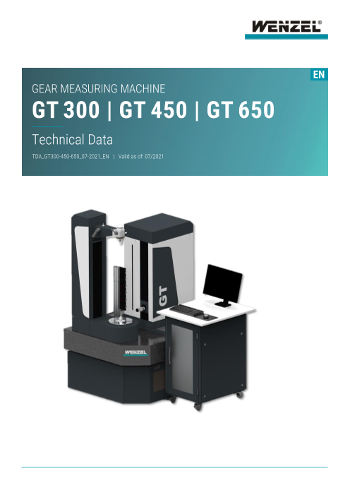
WENZEL社の新しい歯車試験機「GTシリーズ」は、歯車測定技術における高精度の要求を、正確・簡単・迅速に満たすために設計されました。GTシリーズは、優れた人間工学・使いやすさ・広範な測定・分析オプションを特徴としています。歯車や回転対称コンポーネントに最適なソリューションです。
GTシリーズでは、平歯車、円筒歯車、かさ歯車、ころ歯車のほか、はすば歯車、インボリュート歯車を測定および評価できます。
非接触センサーを搭載することもでき、タービンブレードなどの高精度な測定も行えます。
~ソフトウェア パッケージ~
WM|Gearは、WENZEL社の座標測定機でインボリュートのデータ収集と測定を行うための新しいソフトウェア パッケージです。
– 共通評価基準(GDE)のサポート
– 3軸・4軸測定機による測定
– 統計システムとの連携が可能
– 多くの評価パラメータは後からでも変更可能
– 多くのプレゼンテーションパラメータは後からでも変更可能
– 測定結果をPDF形式でアーカイブ
このカタログについて
| ドキュメント名 | WENZEL / 歯車測定器GTシリーズ |
|---|---|
| ドキュメント種別 | 製品カタログ |
| ファイルサイズ | 829.8Kb |
| 登録カテゴリ | |
| 取り扱い企業 | 株式会社シーケービー (この企業の取り扱いカタログ一覧) |
この企業の関連カタログ

このカタログの内容
Page1
EN
GEAR MEASURING MACHINE
GT 300 | GT 450 | GT 650
Technical Data
TDA_GT300-450-650_07-2021_EN | Valid as of: 07/2021
Page2
Technical Data
GT 300 | GT 450 | GT 650
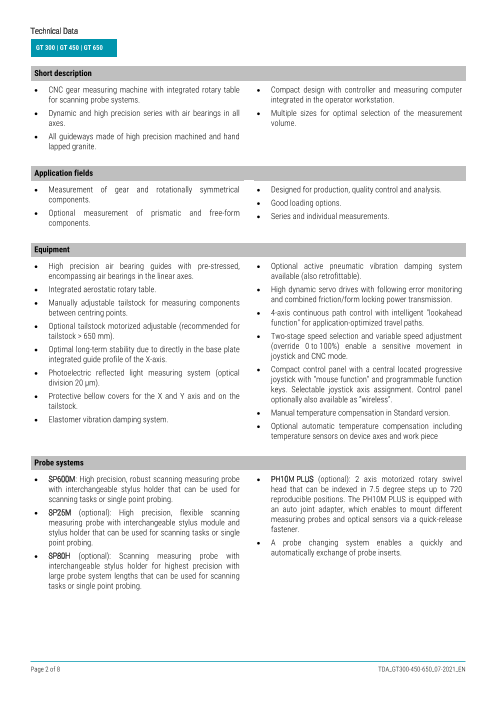
Short description
CNC gear measuring machine with integrated rotary table Compact design with controller and measuring computer
for scanning probe systems. integrated in the operator workstation.
Dynamic and high precision series with air bearings in all Multiple sizes for optimal selection of the measurement
axes. volume.
All guideways made of high precision machined and hand
lapped granite.
Application fields
Measurement of gear and rotationally symmetrical Designed for production, quality control and analysis.
components. Good loading options.
Optional measurement of prismatic and free-form Series and individual measurements.
components.
Equipment
High precision air bearing guides with pre-stressed, Optional active pneumatic vibration damping system
encompassing air bearings in the linear axes. available (also retrofittable).
Integrated aerostatic rotary table. High dynamic servo drives with following error monitoring
Manually adjustable tailstock for measuring components and combined friction/form locking power transmission.
between centring points. 4-axis continuous path control with intelligent "lookahead
Optional tailstock motorized adjustable (recommended for function" for application-optimized travel paths.
tailstock > 650 mm). Two-stage speed selection and variable speed adjustment
Optimal long-term stability due to directly in the base plate (override 0 to 100%) enable a sensitive movement in
integrated guide profile of the X-axis. joystick and CNC mode.
Photoelectric reflected light measuring system (optical Compact control panel with a central located progressive
division 20 µm). joystick with “mouse function” and programmable function
keys. Selectable joystick axis assignment. Control panel
Protective bellow covers for the X and Y axis and on the optionally also available as “wireless”.
tailstock.
Manual temperature compensation in Standard version.
Elastomer vibration damping system.
Optional automatic temperature compensation including
temperature sensors on device axes and work piece
Probe systems
SP600M: High precision, robust scanning measuring probe PH10M PLUS (optional): 2 axis motorized rotary swivel
with interchangeable stylus holder that can be used for head that can be indexed in 7.5 degree steps up to 720
scanning tasks or single point probing. reproducible positions. The PH10M PLUS is equipped with
SP25M (optional): High precision, flexible scanning an auto joint adapter, which enables to mount different
measuring probe with interchangeable stylus module and measuring probes and optical sensors via a quick-release
stylus holder that can be used for scanning tasks or single fastener.
point probing. A probe changing system enables a quickly and
SP80H (optional): Scanning measuring probe with automatically exchange of probe inserts.
interchangeable stylus holder for highest precision with
large probe system lengths that can be used for scanning
tasks or single point probing.
Page 2 of 8 TDA_GT300-450-650_07-2021_EN
Page3
Technical Data
GT 300 | GT 450 | GT 650
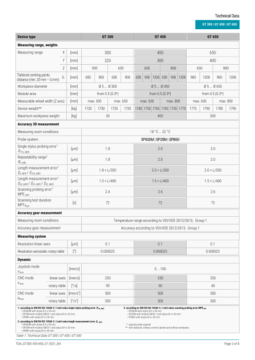
Device type GT 300 GT 450 GT 650
Measuring range, weights
Measuring range X [mm] 300 450 650
Y [mm] 225 300 400
Z [mm] 500 650 650 800 650 800
Tailstock centring points
G [mm] 650 900 650 900 650 900 1200 650 900 1200 900 1200 900 1200
distance (min. 20 mm – G mm)
Workpiece diameter [mm] Ø 5 … Ø 300 Ø 5 … Ø 450 Ø 5 … Ø 650
Module area [mm] from 0.5 (0.3*) from 0.5 (0.3*) from 0.5 (0.3*)
Measurable wheel width (Z axis) [mm] max. 500 max. 650 max. 650 max. 800 max. 650 max. 800
Device weight** [kg] 1720 1730 1725 1735 1740 1750 1765 1745 1755 1770 1775 1790 1780 1795
Maximum workpiece weight [kg] 50 400 500
Accuracy 3D measurement
Measuring room conditions 18 °C … 22 °C
Probe system SP600M | SP25M | SP80H
1
Single stylus probing error
[µm] 1.8 2.0 2.0
PFTU, MPE
2
Repeatability range
[µm] 1.8 2.0 2.0
R0, MPL
2
Length measurement error
[µm] 1.8 + L/350 2.0 + L/350 2.0 + L/350
E0, MPE / E150, MPE
2
Length measurement error
[µm] 1.3 + L/400 1.5 + L/400 1.5 + L/400
E0X, MPE / E0Y, MPE / E0Z, MPE
3
Scanning probing error
[µm] 2.4 2.6 2.6
MPETHP
Scanning test duration
[s] 72 72 72
MPTτHP
Accuracy gear measurement
Measuring room conditions Temperature range according to VDI/VDE 2612/2613, Group 1
Accuracy gear measurement Accuracy according to VDI/VDE 2612/2613, Group 1
Measuring system
Resolution linear axes [µm] 0.1 0.1 0.1
Resolution aerostatic rotary table [°] 0.000025 0.000025 0.000025
Dynamic
Joystick mode
[mm/s] 0 … 100
vmax
CNC mode linear axes [mm/s] 250 250 250
vmax
rotary table [°/s] 95 60 40
CNC mode 2
linear axes [mm/s ] 500 500 500
amax 2
rotary table [°/s ] 300 300 300
1: according to DIN EN ISO 10360-5 / Limit value single stylus probing error PFTU, MPE 3: according to DIN EN ISO 10360-4 / Limit value scanning probing error MPETHP
• SP600M with stylus Ø 5 x 50 mm • SP600M with stylus Ø 5 x 50 mm
• SP25M with module SM25-1 and stylus Ø 4 x 30 mm • SP25M with module SM25-1 and stylus Ø 4 x 30 mm
• SP80H with stylus Ø 5 x 50 mm • SP80H with stylus Ø 5 x 50 mm
2: according to DIN EN ISO 10360-2 / Limit value length measurement error EL, MPE
• SP600M with stylus Ø 5 x 50 mm * special probe required
• SP25M with module SM25-1 and stylus Ø 4 x 30 mm ** with tailstock, without control cabinet and without workpiece
• SP80H with stylus Ø 5 x 50 mm
Table 1: Technical Data GT 300 | GT 450 | GT 650
TDA_GT300-450-650_07-2021_EN Page 3 of 8
Page4
Technical Data
GT 300 | GT 450 | GT 650
Measurement reference temperature GT 300 GT 450 GT 650
Measuring room conditions
Temperature range 18 °C to 22 °C
for length measurement error EL, MPE K
(3D measurement) per hour 1 /h
K
spatial 1 /m
K
per day 2 /d
Temperature range for gear measurement Temperature range according to VDI/VDE 2612/2613, Group 1
Table 2: Measurement reference temperature GT 300 | GT 450 | GT 650
Operating conditions GT 300 GT 450 GT 650
Ambient temperature 15 °C to 30 °C
Relative humidity 40 % to 70 % (non-condensing)
Max. height of the installation site 2000 m over sea level
Electrical connection values Electricity quality according to EN 60204-1:2019-06
Single phase alternating current (1P+N+PE), 115/230 V (±10 %), 50/60 Hz
Electrical power consumption max. 1000 VA
Pneumatic connection values Supply pressure min. 6 bar, max. 10 bar, pre-filtered
with elastomer
vibration damping system Compressed air quality according to DIN ISO 8573-1:2010 [1:3:1]
Air consumption Ø 69 Nl/min Ø 69 Nl/min Ø 69 Nl/min
max. 69 Nl/min max. 69 Nl/min max. 69 Nl/min
Pneumatic connection values Supply pressure min. 6 bar, max. 10 bar, pre-filtered
with pneumatic
vibration damping system Compressed air quality according to DIN ISO 8573-1:2010 [1:3:1]
(optional) Air consumption Ø 85 Nl/min Ø 85 Nl/min Ø 85 Nl/min
max. 100 Nl/min max. 100 Nl/min max. 100 Nl/min
Table 3: Operating conditions GT 300 | GT 450 | GT 650
Specification GT 300 GT 450 GT 650 Unit
Measuring range X 300 450 650 mm
Y 225 300 400 mm
Z 500 650 650 800 650 800 mm
Rotary table diameter C2 Ø 200 Ø 300 Ø 400 mm
Max. workpiece diameter C1 Ø 300 Ø 450 Ø 650 mm
Tailstock G 650 900 650 900 650 900 1200 650 900 1200 900 1200 900 1200 mm
Machine foot print Length L1 1183 1388 1678 mm
(without control cabinet)
Width B1 1079 1229 1429 mm
Height H3 1843 1993 1993 2143 1993 2143 mm
Height H2 1962 2212 1962 2212 1962 2212 2512 1962 2212 2512 2212 2512 2212 2512 mm
Control cabinet (L x W x H) 900 x 770 x 1130 900 x 770 x 1130 900 x 770 x 1130 mm
Required space Length L4 2533 2758 3058 mm
(machine foot print incl.
control cabinet, working and Width B3 2390 2540 2740 mm
danger area) Height H1 2343 2343 2493 2493 2493 2493 2562 2643 2643 2643 2493 2562 2643 2643 mm
Table 4: Dimensions GT 300 | GT 450 | GT 650
Page 4 of 8 TDA_GT300-450-650_07-2021_EN
Page5
Technical Data
GT 300
Figure 1: Layout GT 300
TDA_GT300-450-650_07-2021_EN Page 5 of 8
Page6
Technical Data
GT 450
Figure 2: Layout GT 450
Page 6 of 8 TDA_GT300-450-650_07-2021_EN
Page7
Technical Data
GT 650
Figure 3: Layout GT 650
TDA_GT300-450-650_07-2021_EN Page 7 of 8
Page8
INNOVATION MEETS TRADITION
The WENZEL Group is a market leader in innovative power generation and medicine. WENZEL looks at today
Metrology. WENZEL offers a comprehensive product on an installed base of more than 10,000 machines
portfolio in the fields of Coordinate Metrology, worldwide. Subsidiaries and agencies in more than 50
Computed Tomography and Optical High Speed countries support sales and provide after -sales service for
Scanning. The technology of WENZEL is used in all our customers. The WENZEL Group today employs more
industries, including the automotive sector, aeronautics, than 600 people.
YOUR LOCAL CONTACT PERSON
WENZEL GROUP GMBH & CO. KG
Werner-Wenzel-Straße
97859 Wiesthal
Phone: +49 6020 201-0
E-Mail: info@wenzel-group.com
We are there for you worldwide. You can find our subsidiaries, sales and service
partners at www.wenzel-group.com.
W ENZEL Group GmbH & Co. KG | Werner-Wenzel-Straße | 97859 Wiesthal | Germany
Phone: +49 6020 201-0 | Fax: +49 6020 201-1999 | E-Mail: info@wenzel-group.com www.wenzel-group.com
TDA_GT300-450-650_07-2021_EN | © 2021 WENZEL Group GmbH & Co. KG
Subject to changes in design and specification without prior notice.


