


放流タイプ(Discharge Type)「HST」 ・絶縁タイプ(Insulation Type)「ZST」
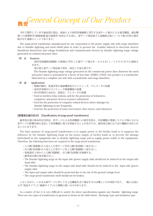
当社で製作しています耐雷変圧器は、落雷により商用受電線路に発生する雷サージ電圧による電気機器、通信機器への誘導障害(絶縁破壊,電圧破壊等)を防止する為に、雷サージ吸収素子と混触防止板(シールド板)付変圧器を組合せた電源ユニットであります。
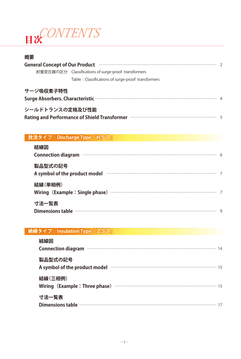
掲載内容
・耐雷変圧器の区分
・サージ吸収素子特性
・シールドトランスの定格及び性能
・放流タイプ
・絶縁タイプ
◆詳細はカタログをダウンロードしご覧いただくか、お気軽にお問い合わせ下さい。
このカタログについて
| ドキュメント名 | 耐雷変圧器 放流タイプ/絶縁タイプ |
|---|---|
| ドキュメント種別 | 製品カタログ |
| ファイルサイズ | 4.5Mb |
| 登録カテゴリ | |
| 取り扱い企業 | 株式会社久野電機製作所 (この企業の取り扱いカタログ一覧) |
この企業の関連カタログ


このカタログの内容
Page1
★製品「Products」★
移動用小型変圧器 [ Portable and small safety transformer ]
仮設坑内用キュービクル [ Cubicle for temporary work site ]
モールド変圧器 [ Molded transformer ]
耐雷変圧器 [ Surge-proof transformer ]
UL規格認証変圧器 [ UL Spec. certified transformer ]
CE規格認証変圧器 [ EN Spec. certified transformer ]
耐圧防爆型変圧器 [ Explosion-proof transformer]
励磁突入電流低減変圧器 [ Inrush current reduction transformer ] 耐雷変圧器
K-Factor定格変圧器 [ K-Factor rated transformer ]
・放流タイプ(Discharge Type)「HST」
株式会社 久野電機製作所 ・絶縁タイプ(Insulation Type)「ZST」
HISANO ELECTRIC WORKS LTD.
本社工場:〒 848-0022 佐賀県伊万里市大坪町字猪子谷乙 5590-47
Head Office:Postal Code 848-0022 , 5590-47,Inokodani-otsu,
Otsubo-cho,Imari City,Saga Prefecture,Japan
TEL(0955)26 - 2558 FAX(0955)26 - 3083
http://www.hisano.co.jp E-mail sales@hisano.co.jp
東京工場:〒 243-0807 神奈川県厚木市金田 1045
Tokyo Office:Postal Code 243-0807 , 1045 Kaneda,Atsugi City,
Kanagawa Prefecture,Japan
TEL(046)225 - 7311 FAX(046)225 - 7312
代理店 [ Agency ]
株式会社 久野電機製作所
Hisano Electric Works LTD.
2009年度版
Page2
CONTENTS 製品の運搬、設置の際は、落下、転倒させないよう十分に注意して下さい。
目次 けがや破損の原因になります。
Be very cautious in the transporting or installing of the product. Dropping or overturning
the product may cause injuries or damages.
概要 注 意 製品の運搬、設置の際は、製品の上にのらないでください。
General Concept of Our Product ……………………………………………………………………………… 2 Caution けがや破損の原因になります。
耐雷変圧器の区分 Classifications of surge-proof transformers Do not get on the product to avoid injuries or damages when transporting or installing it.
Table:Classifications of surge-proof transformers
通電中は変圧器のコイル・鉄心が高温になります。
手を触れる際は電源を切って十分に時間をおいてから行ってください。
サージ吸収素子特性 やけどの危険があります。
Surge Absorbers. Characteristic ………………………………………………………………………………… 4 The transformer’s coil and iron core become very hot with high temperatures while the
power is flowing.
シールドトランスの定格及び性能 Turn off the power supply and take sufficient time before touching the product to avoid
the danger of getting burnt.
Rating and Performance of Shield Transformer ………………………………………………………… 5
充電部の端子、内部配線、変圧器には人身や導電物が触れないようにしてください。
感電事故につながり危険です。
放流タイプ Discharge Type「HST」 Maintain the terminals of the charging part, internal wirings, and the transformer
untouched by any person or by any conductive material to avoid the danger of electric
結線図 shock accidents.警 告
Connection diagram ………………………………………………………………………………………… 6 Warning 保守・点検で製品に触れる場合は、必ず電源を切り、無電圧を確認のうえ、端子を接地
放電してから作業を行ってください。
製品型式の記号 Make sure to turn off the power supply, check for no-voltage, and ground-discharge the
A symbol of the product model ………………………………………………………………………… 7 terminals before touching the product for the maintenance & inspection works.
結線(単相例) 製品の設置、保守・点検が終了したら、保護カバー、ケースカバーは出荷時の取付状態
に必ず戻してください。
Wiring(Example: Single phase) ……………………………………………………………………… 7
Make sure to put back the protection cover and case cover to the as-mounted positions
寸法一覧表
at the time of shipment when the installation and maintenance & inspection of the
product are completed.
Dimensions table ……………………………………………………………………………………………… 9
接地は、結線(P7,P15)の記載に従って行ってください。
接地方法が異なると製品の機能が低下することがあります。
絶縁タイプ Insulation Type「ZST」
Grounding shall be carried out in accordance with the procedures described in “wiring”
(Page 7, and 15).
Grounding done in manners different from the specified procedures may lead to the
結線図 deterioration of the product performance.
Connection diagram ……………………………………………………………………………………… 14
過負荷運転しないでください。
製品型式の記号 定格を超えて運転すると火災につながる恐れがあります。
A symbol of the product model ……………………………………………………………………… 15 Do not perform overloaded operations. Operations with loads over the rated capacity
may cause a fire.
結線(三相例) 注 意 充電部端子の締め忘れに注意してください。
Wiring(Example: Three phase)
Caution
…………………………………………………………………… 15 接触不良により異常発熱、火災につながるおそれがあります。
Be careful not to forget to tighten the terminals of the charging part. Contact failure may
寸法一覧表 lead to the generation of abnormal heat, or a fire.
Dimensions table …………………………………………………………………………………………… 17 製品に結露や水が直接かからないようにしてください。
漏電により感電事故につながり危険です。
Maintain the product free from dew condensation or direct water spraying to avoid the
注 意 danger of electric shock accidents due to leakage.
Caution
−1− −22−
Page3
General Concept of Our Product
概要
当社で製作しています耐雷変圧器は、落雷により商用受電線路に発生する雷サージ電圧による電気機器、通信機
器への誘導障害(絶縁破壊,電圧破壊等)を防止する為に、雷サージ吸収素子と混触防止板(シールド板)付変圧器を
組合せた電源ユニットであります。
The surge-proof transformer manufactured by our corporation is the power supply unit with surge absorbers
due to thunder lightning and earth shield plate in order to prevent the troubles induced to electronic devices
(insulation destruction and voltage breakdown) and communication devices by thunder lightning surge voltage
generated on commercial power lines.
・特 長 Features
商用受電線路(電線路~大地間)に発生した雷サージ電圧を-60dB(1/1000)以下に減衰さ
せます。
変圧器と雷サージ吸収素子部を一体化した変圧器です。
The thunder lightning surge voltage generated on the commercial power lines (between the earth
and power lines) is attenuated by a factor of less than -60dB(1/1000). Our product is a transformer
fabricated as a complete one unit with a transformer and surge absorbers.
・用 途 Applications
・無線中継所,変電所等の電源機器及びコンピュータ,テレメータの保護
・雷害多発地区のコンピュータ関連機器の保護
・河川管理用の水位計,流量計,テレメータの保護
・ Used at wireless relay stations, and for the protection of telemeters,
computers, and power devices at power substations.
・Used for the protection of computer-related devices where damages by
thunder lightning occurs frequently.
・Used for the protection of water level meters, flow meters, and telemeters.
【耐雷変圧器の区分】 [Classifications of surge-proof transformers]
耐雷変圧器の基本的な目的は、雷サージによる負荷機器への被害を防止、負荷機器の電源システム全体に与える
雷サージの影響を抑え安定して負荷機器に電力を供給することがあげられ、耐雷変圧器には下記の機能が求められ
ることになります。
The basic purpose of surge-proof transformers is to supply power to the facility loads is to suppress the
influence by the thunder lightning surge on the power supply of facility loads m, to prevent the damage
beforehand on the equipments due to thunder lightning surge and to supply power stably to the equipments.
Therefore, the following functions are required to the surge-proof transformer.
・入力側(電源側)から侵入した雷サージを出力側(負荷側)へ流さない。
・出力側(負荷側)から侵入した雷サージを入力側(電源側)へ流さない。
・接地電位上昇から入力側(電源側)、出力側(負荷側)を保護する。
・耐雷変圧器自身を壊さない。
・T he thunder lightning surge on the input side (power supply side) should not be induced on the output side
(load side).
・T he thunder lightning surge on the output side (load side) should not be induced to the input side (power
supply side).
・The input and output sides should be protected due to the rise of the ground voltage level.
・The surge-proof transformer itself should not be broken.
しかしながら、いかなる雷サージに対しても上記機能を全て満足するのは難しいのが現状であり、一般には表に
示す「放流タイプ」と「絶縁タイプ」の2種類の使い分けがあります。
As a matter of fact it is very difficult to satisfy the above specifications against any thunder lightning surge.
There are two types of transformers in general as shown in the table below: discharge type and insulation type.
-2-
Page4
表 耐雷変圧器の区分 Table Classifications of Surge-Proof Transformers
放流タイプ Discharge Type「HST」 絶縁タイプ Insulation Type「ZST」
・対 地間に挿入されたアレスタにより電源側から侵 ・接 地電位上昇時アレスタの放流による逆流入が無
入するコモンモードサージに対し耐雷変圧器の保 いため電源側機器や他の需要家へ雷サージ電流が
護をする。 流れ込むことが無い。
・A transformer is protected against common- ・ No thunder lightning surge will not flow in to the
mode surge induced from the power supply side electrical devices or to other customers because
through the arrester inserted to the ground. of the non-reverse current due to the discharge
from the arrester in case of the rise of the ground
voltage.
長
・電 源側から侵入したコモンモードサージに対して ・電 源側からのノーマルモードサージをアレスタの
所 入力側対地間のアレスタでアレスタの制限電圧ま
放流により負荷側への流入を制限する。
で減衰させた後、さらに耐雷変圧器の二重シール
ドによって更に減衰させるため負荷側への雷サー
ジ減衰量は大きい。
・ After the surge voltage is attenuated up to ・T he current flow on the power supply side is
the controlled voltage of the arrester by the controlled by the discharge of the normal-mode
arrester between the input side and the ground surge through the arrester on the power supply
against the common-mode surge induced from side.
the power supply side, the attenuation by the
thunder lightning surge on the loads due to the
attenuation by the double shield of the surge-
proof transformer is large.
・接 地極電位上昇により対地間アレスタで雷サージ ・対地間にアレスタが挿入されていないため電源側
電流が電源側へ放流されることで電源側の機器や から侵入するコモンモードサージを耐雷変圧器で直
他の需要家に被害が及ぶ可能性がある。 接受けることになり、またサージ減衰量も耐雷変圧
器のみの減衰量となる。
・ It is possible to damage the devices on the power ・ The common-mode surge is directly affected to
supply side or customers due to the discharge the surge-proof transformer due to the induced
of thunder lightning surge current on the power current from the power supply side because no
supply side by the rise of the ground voltage arrester is inserted between the transformer and
短 level. the ground. The attenuation of the surge is the
所 one by the surge-proof transformer only.
・電 源側の対地間にアレスタが挿入されていないた
め電源側からのコモンモードサージに対し耐雷変
圧器の保護が無く、電源側に設置される機器には
耐雷変圧器と絶縁協調をとる必要がある。
・ No protection is made on the surge-proof
transformer against the common-mode surge
current from the power supply side because no
arrester is inserted between the transformer and
the ground. Therefore, the devices installed on
the power supply side should be insulated from
the surge-proof transformer
-3-
Merits Demerits
Page5
Surge Absorbers. Characteristic
サージ吸収素子特性
・避雷器:音羽電機工業株式会社製 LGL 酸化亜鉛形低圧タイプ
Arrester:A product made in Otowa LGL Zinc oxide resister type
特性 制限電圧(V) 放電耐量
Charac- Residual Current impulse
teristic 最大許容電圧(V)
Maximum permissible
動作開始電圧
voltage(V) withstand capability
voltage(V)
Reference
公称放電電流10kA
雷インパルス電流
AC
voltage(V)
Discharge current
Lightning impulse
型式 (8/20μs)
Current
Type (8/20μs)
GL-L1F 110 250±12% Less than 700
GL-L2F 230 500±12% Less than 1200 20kA Twice
GL-L4F 440 1000±12% Less than 2500
・サージアブソーバ:Panasonic製 ZNR Eタイプ
surge absorbers:A product made in Panasonic ZNR EType
特性
Charac- 最大許容電圧(V) サージ電流耐量
teristic バリスタ電圧(V) Maximum permissible
最大制限電圧(V)
Barista voltage (V) voltage(V)
Maximum Residual
Surge
voltage (V)
Capability
型式 AC (8/20μs)
type
ERZC32EK271 270 175 455
ERZC32EK511 510 320 845 20kA Twice
ERZC32EK112 1100 680 1815
サージアブソーバ 避雷器
Surge absorbers Arrester
-4-
Page6
Rating and Performance of Shield Transformer
シールドトランスの定格及び性能
回路 Circuit 単 相 三 相
項目 Item Single-phase Three-phase
周波数 Frequency 50/60Hz
1次電圧 Pri. voltage 100V or 200V 200V or 400V
2次電圧 Sec. voltage 100V or 200V 200V or 400V
定格容量 Rating capacity 0.5 〜 50kVA 5 〜 100kVA
耐熱クラス Less than 5kVA B Class
Insulation class H Class More than 5kVA H Class
温度上昇限度 Temperature rise limit B Class 75K ,H Class 140K
冷却方式 Cooling method 乾式自冷式 Natural cooling dry type
極 性 Polarity 減極性 Subtruct —
0.5 〜 3kVA —
電圧変動率 5kVA Less than 4% Less than 4.5%
Voltage regulation 7.5 〜 25kVA Less than 4%
More than 30kVA Less than 3% Less than 3%
0.5kVA More than 91% —
1 〜 2kVA More than 92% —
効率
Efficiency 3kVA More than 94% —
5 〜 15kVA More than 95% More than 95%
More than 20kVA More than 96% More than 96%
1次-2次,大地間
商用周波絶縁強度 Between Pri. and Sec.,Earth AC 10kV 1 minute
Dielectric insulation ※
strength 2次-1次,大地間
Between Sec. and Pri. Earth AC 3kV 1 minute
インパルス絶縁強度
Impulse insulation 1次-2次,大地間
strength Between Pri. and Sec.,Earth
30kV (1.2/50μs) ※
More than100MΩ
絶縁抵抗 Insulation resistance DC 500V メガー By DC 500V megger端子相互間 A terminal aspect each ※
other interval
サージ減衰量 平衡 Common mode
Surge attenuation (線とアース間) Less than -60dB(1/1000)at 1.2/50μs 10kV ※Between line and a earth
周囲温度
Ambient temperature -20℃〜 +40℃
湿 度
Humidity Less than 90%使用条件
Terms of use 標 高
Meters above the sea level Not exceed 1000m
使用場所
use place 屋内 Indoor use
注:1.※印の試験時はサージ吸収素子を外して下さい。
2.F種モールド型及び上記標準(電圧、容量)以外も製作致します。
N.B. 1.Remove surge absorbers when the test measurement marked ※ is made.
2.T ransformers other than the above-mentioned standard types (voltage and capacity) or F-class molded
types are to be manufactured.
-5-
Page7
放流タイプ Discharge Type「HST」
・動 作 Operation
商用受電線路U〜V間 及び大地間に発生した雷サージ電圧の線間(U,V間)に生じた電圧は、サージア
ブソーバZ1によりバリスタ電圧まで低減されます。電線路〜大地間に生じた電圧は、避雷器(アレスタ)L
1,L2にて接地回路を通して大地に放電され、これにより雷サージエネルギーのほとんどが吸収されます。
一部吸収されなかったエネルギーが変圧器2次側に誘導されますが、変圧器の1〜2次間に入れた混触防止
板の静電シールドにより、2次への誘導を極力低減させ、さらに2次側に入れたサージアブソーバZ2及び、
エネルギー吸収用コンデンサCにより雷サージエネルギーを吸収させます。これらの雷サージ吸収素子を付
属させない変圧器のみの高耐圧絶縁変圧器では、雷サージエネルギーを吸収する事が困難で有り、2次側に
大きな誘導サージ電圧を誘起させ、機器の保護が不十分になります。
The thunder lightning surge voltage generated between U and V on the commercial power lines or
between the earth and power lines is attenuated up by the absorber, Z1, to the varistor voltage. The voltage
generated between power lines and the earth is discharged to the earth through ground circuits made of
a thunder lightning rod (arrester),L1 and L2. The most of thunder lightning energy is absorbed by these
circuits. A part of energy not absorbed will be induced on the secondary side of a transformer, but the
induction on the secondary side will be attenuated as much as possible by the static shieldof the earth
shield plate inserted between the primary and secondary sidesof a transformer.Furthermore, the surge
absorber, Z2, and the energy-absorbing capacitor, C, inserted on thesecondary side will absorb the surge
energy by thunder lightning.
R egarding the high-voltage insulation transformer without surge absorbing elements due to thunder
lightning, it is very difficult to absorb thunder lightning surge energy and not sufficient to protect devices
on the secondary side due to the induction of large surge voltage.
1 結線図 Connection diagram
代表的な回路でありますが単相三線式,スコット、V-逆V等の結果も可能です。
It is possible to make the wiring such as single-phase 3w, Scott, Inverse V as typical circuits.
-6-
Page8
2 製品型式の記号 A symbol of the product model
HST□-□□-□□
2次電圧 1:100V, 2:200V
Sec.voltage
1次電圧 1:100V, 2:200V, 4:400V
Pri.voltage
容量(kVA)
Capacity
相 数 S:単相, Y:三相
Phase Single-phase Three-phase
トランス構造 無:裸, Ⅰ:屋内通気ケース入, S:屋外ケース入
Transformer structure Nothing:Non case I : Indoor ventilation case S:Outdoor Case
例) 三相,50kVA,裸,1次電圧 200V, 2次電圧 200V
HST-Y50-22
Example) Three-phase,50kVA,Non case,Pri. voltage:200V,Sec. voltage:200V
HST-Y50-22
3 結線(単相例) Wiring(Example :Single phase)
① 配線について Regarding Wiring
配線間でサージの移行を防ぐため、1次側配線と2次側配線は出来るだけ離して配線して下さい。
I n order to prevent the surge induction between wirings, the wirings on the primary and secondary sides
must be separated as much as possible.
-7-
Page9
② 接地について Regarding the earth
(1)接地線サイズは、5. 5sq以上を使用して下さい。
(2)Ep端子は独立端子,Es端子は変圧器本体、混触防止板を一括した端子です。
(3)E p接地は、耐雷トランスの入力側避雷器の放電電流を、大地に放流する為の接地で避雷器が動作した時、
非常に高電位となります。
この為、Ep接地は他の負荷設備の接地やEs接地から少なくとも2m以上離した電源側の
(B種)接地点の方へ接地を取り、接地抵抗は、出来る限り30Ω以下として下さい。(※注)
(4)E s接地は、なるべく負荷設備の据付け場所に近い所に取り、接地抵抗は出来る限り100Ω以下として下
さい。
(5) 設置場所の環境により、Ep・Es端子を離して接地出来ない場合は、雷サージ減衰性能が下がりますので
ご了承下さい。
この場合は出来るだけ接地抵抗を低くとり、雷サージの移行を最小限に抑えるようにして下さい。
(6)筐体接地はEs端子を使用して下さい。
(1)Grounding wires should be used more than 5.5sq
(2)E p Terminal is an independent terminal. Es Terminal is a terminal into which the terminals of the
transformer's main body and the earth shield plate are integrated.
(3)T he Ep grounding will be at high voltage when the thunder lightning rod is operated as discharging
ground in order to discharge a large amount of current when thunder lightning rod of the input side is
discharged. Due to this the Ep ground must be separated at least 2 meters away from the ground of other
facility loads or the Es ground, and also be grounded near the B class ground point of the power side.
The ground resistor must be less than 30Ω. (※Note)
(4)T he Es ground must be made as close as possible near the facility loads. The ground resistor should be
less than 100Ω.
(5)I t shall be acknowledged that the thunder surge damping performance gets deteriorated when Ep and Es
cannot be grounded remotely with each other because of the surrounding conditions at the installation
site.
I n such a case, try to minimize the thunder surge transfer by providing the grounding resistance as low as
possible.
(6)The Es terminal should be used for the ground of the housing
③ サージ吸収素子について Regarding surge absorbers
耐 圧試験、絶縁抵抗測定において、避雷器はワンタッチ着脱式になっていますので必ず取り外して下さい。
サージアブソーバは結線を取り外します。
When voltage-resistant and insulation resistance measurement are made, the Thunder lightning rod should
be removed as easily be removed by clicking.
The surge absorbers should be removed from the circuits.
④ 襲雷時には、危険ですのでむやみにケース等触れないようにして下さい。
Caution should be made not to touch the housing in case of thunder lightning flash.
※注) 等電位ボンディング方式、環状接地方式などを施された建物内においては接地を離す必要はありません。
(共通接地で可)
※Note) The remote grounding of Ep and Es is not necessary in the buildings where Equipotential bonding
method or Ring earth electrode method is applied. (Common grounding will do.)
-8-
Page10
放流タイプ Discharge Type
単相変圧器(盤内収納用、裸)
Single Phase Transformer(Non Case)
型 式
容量 寸 法 Dimension 端子 端子 外観図 質量
Type
Capacity Terminal Terminal Outside Mass
(kVA) X Y1 Y2 Z XS YS D (100V) (200V) View (kg)
HST-S0.5-□ 0.5 220 135 165 310 150 110 8 M5 M6 Fig 1 16
H S T - S 1 - □ 1 220 135 165 310 150 120 8 M5 M6 Fig 1 20
HST-S1.5-□ 1.5 360 135 165 340 180 120 10 M5 M6 Fig 2 30
H S T - S 2 - □ 2 360 135 165 445 160 120 10 M5 M6 Fig 2 40
H S T - S 3 - □ 3 360 140 170 445 160 130 10 M5 M6 Fig 2 46
H S T - S 5 - □ 5 360 150 170 410 180 160 10 M8 M6 Fig 3 55
HST-S7.5-□ 7.5 360 150 170 410 180 175 10 M8 M6 Fig 3 65
HST-S10-□ 10 400 205 220 480 150 280 12 M10 M8 Fig 4 90
HST-S15-□ 15 400 205 230 550 150 280 12 M12 M8 Fig 4 105
HST-S20-□ 20 500 260 270 550 150 300 15 M12 M10 Fig 4 145
HST-S25-□ 25 500 260 270 570 150 300 15 M12 M12 Fig 4 155
HST-S30-□ 30 500 290 290 590 150 310 15 M12 M12 Fig 4 170
HST-S40-□ 40 550 270 270 680 200 310 15 Fig b Fig c Fig 5 200
HST-S50-□ 50 550 280 280 710 200 330 15 Fig a Fig c Fig 5 225
*寸法単位 mm
*The physical dimensions are in mm
-9-
Page11
-10-
Page12
放流タイプ Discharge Type
三相変圧器(盤内収納用、裸)
Three Phase Transformer (Non Case)
型 式
容量 寸 法 Dimension
端子(200V) 端子(400V) 端子 質量
Type
Capacity Terminal Terminal Terminal Mass
(kVA) X Y1 Y2 Z XS YS D 1次 2次 1次 2次 Ep,Es (kg)
H S T- Y 5 - □ 5 460 205 245 495 270 150 10 M5 M6 M5 M6 M6 80
HST-Y7.5-□ 7.5 460 210 250 495 270 160 10 M5 M6 M5 M6 M6 90
HST-Y10-□ 10 470 205 245 585 290 240 12 M5 M6 M5 M6 M6 120
HST-Y15-□ 15 470 215 255 585 290 260 12 M6 M6 M5 M6 M6 140
HST-Y20-□ 20 520 225 265 610 320 260 15 M8 M8 M5 M6 M6 160
HST-Y25-□ 25 520 225 265 610 320 275 15 M8 M8 M6 M6 M6 175
HST-Y30-□ 30 520 230 270 610 320 295 15 M10 M10 M6 M6 M6 195
HST-Y40-□ 40 560 230 270 640 350 300 15 M10 M10 M8 M8 M8 225
HST-Y50-□ 50 590 240 280 640 370 320 15 M12 M12 M8 M8 M8 255
HST-Y75-□ 75 670 320 340 760 400 330 15 M12 M12 M10 M10 M10 380
HST-Y100-□ 100 700 320 340 840 440 340 15 M12 M12 M12 M12 M10 490
*寸法単位 mm
*The physical dimensions are in mm
-11-
Page13
放流タイプ Discharge Type
単相変圧器(屋内通気ケース入)
Single Phase Transformer(Indoor Ventilation Case)
型 式
容量 寸 法 Dimension 質量
Type
Capacity Mass
(kVA) X Y Z XS YS (A×B) D (kg)
HSTI-S0.5-□ 0.5 41
H S T I - S 1 - □ 1 400 400 450 340 330 (60×200) 35 45
HSTI-S1.5-□ 1.5 55
H S T I - S 2 - □ 2 74
H S T I - S 3 - □ 3 80
500 450 550 440 380 (60×250) 35
H S T I - S 5 - □ 5 115
HSTI-S7.5-□ 7.5 125
HSTI-S10-□ 10 145
HSTI-S15-□ 15 600 550 650 540 480 (60×250) 40 165
HSTI-S20-□ 20 195
HSTI-S25-□ 25 215
600 600 700 540 530 (80×250) 54
HSTI-S30-□ 30 235
HSTI-S40-□ 40 280
650 650 750 590 580 (80×250) 68
HSTI-S50-□ 50 310
標準塗装色:5Y7/1 [指定色の場合、御指示下さい] *寸法単位 mm
Standard paint color:5Y7/1 [Otherwise color should be specified] *The physical dimensions are in mm
×
×
-12-
Page14
放流タイプ Discharge Type
三相変圧器(屋内通気ケース入)
Three Phase Transformer (Indoor Ventilation Case)
型 式
容量 寸 法 Dimension 質量
Type
Capacity Mass
(kVA) X Y Z XS YS (A×B) D (kg)
HSTI -Y5 -□ 5 120
550 450 600 490 380 (60×250) 35
HSTI-Y7.5-□ 7.5 130
HSTI-Y10-□ 10 165
600 500 650 540 430 (60×250) 40
HSTI-Y15-□ 15 185
HSTI-Y20-□ 20 210
HSTI-Y25-□ 25 650 550 700 590 480 (60×250) 40 225
HSTI-Y30-□ 30 245
HSTI-Y40-□ 40 650 550 700 590 480 (60×250) 54 280
HSTI-Y50-□ 50 700 600 700 640 530 (80×300) 54 315
HSTI-Y75-□ 75 750 600 765 680 530 (80×400) 68 440
HSTI-Y100-□ 100 800 650 865 730 580 (80×400) 68 560
標準塗装色:5Y7/1 [指定色の場合、御指示下さい] *寸法単位 mm
Standard paint color:5Y7/1 [Otherwise color should be specified] *The physical dimensions are in mm
×
×
-13-
Page15
絶縁タイプ Insulation Type「ZST」
・動 作 Operation
1次側の端子間(ノーマルモード)に発生した雷サージ電圧は、避雷器(アレスタ)により制限電圧まで低減
されます。その電圧が変圧器2次側に誘導されますが、さらに変圧器の1〜2次間に挿入した混触防止板の
静電シールドにより2次側への誘導(コモンモード)を-60dB(1/1000)まで低減させる構造になっ
ています。
The induced surge voltage due to thunder lightning flash on the primary side is attenuated up to the
controlled voltage by the thunder lightning arrester inserted, but it will be induced(Common mode)on
the secondary side. The earth shield plate inserted between the primary and secondary sides is designed
so as to attenuate the induction up to -60dB (1/1000)
1 結線図 Connection diagram
-14-
Page16
2 製品型式の記号 A symbol of the product model
ZST□-□□-□□
2次電圧 1:100V, 2:200V
Sec.voltage
1次電圧 1:100V, 2:200V, 4:400V
Pri.voltage
容量(kVA)
Capacity
相 数 S:単相, Y:三相
Phase Single-phase Three-phase
トランス構造 無:裸, Ⅰ:屋内通気ケース入, S:屋外ケース入
Transformer structure Nothing:Non case I : Indoor ventilation case S:Outdoor Case
例) 三相,50kVA,裸,1次電圧 200V, 2次電圧 200V
ZST-Y50-22
Example) Three-phase,50kVA,Non case,Pri. voltage:200V,Sec. voltage:200V
ZST-Y50-22
3 結線(三相例) Wiring(Example :Three phase)
① 配線について Regarding wiring
配線間でサージの移行を防ぐため、1次側配線と2次側配線は出来るだけ離して配線して下さい。
I n order to prevent the surge induction between wirings, the wirings on the primary and Secondary sides
must be separated as much as possible.
-15-
Page17
② 接地について Regarding the earth
(1)接地線サイズは、5. 5sq以上を使用して下さい。
(2)E端子は変圧器本体、混触防止板を一括した端子です。
(3)E 端子は、なるべく負荷設備の据付場所に近い所に取り、接地抵抗は出来る限り100Ω以下として下さい。
(4)筐体接地はE端子を使用して下さい。
(1)Grounding wires should be used more than 5.5sq.
(2)The E terminal is integrated as one connection of the transformer itself and the earth shield plate.
(3)T he E grounding should be made as close as possible to the location of the facility loads, and the ground
resistor should be less than 100Ω.
(4) The E terminal should be used for the ground of the housing.
③ サージ吸収素子について Regarding surge absorbers
耐圧試験、絶縁抵抗測定において、避雷器はワンタッチ着脱式になっていますので必ず取り外して下さい。
W hen voltage-resistant and insulation resistance measurement are made, the Thunder lightning rod should
be removed as easily be removed by clicking.
④ 襲雷時には、危険ですのでむやみにケース等触れないようにして下さい。
Caution should be made not to touch the housing in case of thunder lightning flash.
※注) 変圧器の2次側に漏電遮断器ELCBを使用される場合の機能接地(一線接地)はE端子に接続してください。
※Note) When the electrical leakage breaker, ELCB, is used on the secondary side of the transformer, the
ground (one wire ground) should be connected the E terminal.
※注) 等電位ボンディング方式、環状接地方式などを施された建物内においては接地を離す必要はありません。
(共通接地で可)
※Note)T he remote grounding of Ep and Es is not necessary in the buildings where Equipotential bonding
method or Ring earth electrode method is applied. (Common grounding will do.)
屋内用、裸
Non case
屋外防雨ケース入(特殊品)
Outdoor,Rain proof case
-16-
Page18
絶縁タイプ Insulation Type
単相変圧器(盤内収納用、裸)
Single Phase Transformer(Non Case)
型 式
容量 寸 法 Dimension 端子 端子 外観図 質量
Type
Capacity Terminal Terminal Outside Mass
(kVA) X Y1 Y2 Z XS YS D (100V) (200V) View (kg)
ZST-S0.5-□ 0.5 220 120 120 310 150 110 8 M6 M6 Fig 1 16
Z S T - S 1 - □ 1 220 125 125 310 150 120 8 M6 M6 Fig 1 20
ZST-S1.5-□ 1.5 360 135 135 340 180 120 10 M6 M6 Fig 2 30
Z S T - S 2 - □ 2 360 135 135 445 160 120 10 M6 M6 Fig 2 40
Z S T - S 3 - □ 3 360 140 140 445 160 130 10 M6 M6 Fig 2 46
Z S T - S 5 - □ 5 360 160 160 410 180 160 10 M8 M6 Fig 3 60
ZST-S7.5-□ 7.5 360 170 170 410 180 175 10 M8 M6 Fig 3 70
ZST-S10-□ 10 400 210 210 480 150 280 12 M10 M8 Fig 4 90
ZST-S15-□ 15 400 210 210 550 150 280 12 M12 M8 Fig 4 110
ZST-S20-□ 20 450 240 240 550 150 300 15 M12 M10 Fig 4 135
ZST-S25-□ 25 450 240 240 590 150 300 15 M12 M12 Fig 4 155
ZST-S30-□ 30 450 265 265 590 150 310 15 M12 M12 Fig 4 175
ZST-S40-□ 40 550 260 260 680 200 310 15 Fig b Fig c Fig 5 215
ZST-S50-□ 50 550 270 270 710 200 330 15 Fig a Fig c Fig 5 245
*寸法単位 mm
*The physical dimensions are in mm
-17-
Page19
-18-
Page20
絶縁タイプ Insulation Type
三相変圧器(盤内収納用、裸)
Three Phase Transformer (Non Case)
型 式
容量 寸 法 Dimension 端子 端子 端子 質量
Type
Capacity Terminal Terminal Terminal Mass
(kVA) X Y1 Y2 Z XS YS D (200V) (400V) E (kg)
Z S T - Y 5 - □ 5 420 170 170 460 250 140 10 M6 M6 M6 80
ZST-Y7.5-□ 7.5 420 180 180 460 250 155 10 M6 M6 M6 90
ZST-Y10-□ 10 450 180 180 520 280 155 10 M6 M6 M6 120
ZST-Y15-□ 15 450 190 190 520 280 175 10 M6 M6 M6 140
ZST-Y20-□ 20 470 220 220 570 280 280 12 M8 M6 M6 160
ZST-Y25-□ 25 470 230 230 570 280 300 12 M8 M6 M6 175
ZST-Y30-□ 30 500 250 250 580 280 310 12 M10 M6 M6 195
ZST-Y40-□ 40 550 250 250 610 320 300 15 M10 M8 M8 225
ZST-Y50-□ 50 550 260 260 610 320 320 15 M12 M8 M8 255
ZST-Y75-□ 75 650 285 285 750 400 330 15 M12 M10 M10 380
ZST-Y100-□ 100 680 290 290 830 440 340 15 M12 M12 M10 490
*寸法単位 mm
*The physical dimensions are in mm
-19-